Parker Hannifin
Use the information in Table 54 to select a cable and/or vendor other than
those described previously.
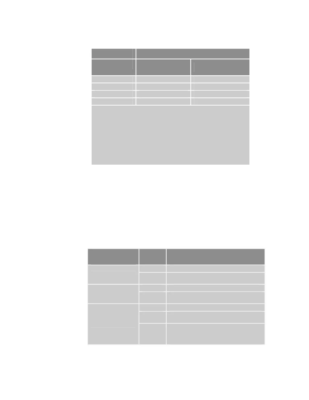
Bus Cable
Bus length [m] Length-Related
Resistance [mΩ/m]
Wire Gauge (mm2)
0 to 40 < 70 24 AWG (0.25 to 0.34)
40 to 300 < 60 22 AWG (0.34 to 0.6)
300 to 600 < 40 20 AWG (0.5 to 0.6)
600 to 1000 < 26 18 AWG (0.75 to 0.8)
Note
Recommended cable AC parameters: 120 Ω impedance and 5-ns/m specific line
delay.
Termination resistor value should match the cable impedance value, typically
120Ω impedance.
See Table 53 for bit-rate de-rating and cable lengths.
For proper shielding requirements, see Error! Reference source not found. on
page Error! Bookmark not defined..
For more information on selecting cables, see the CANopen spec DR303 –
“CANopen Cabling and Connector Pin Assignment”, www.canopen.org/canopen.
Table 54 CANopen Bus-Cable Specifications
CANopen Electrical Installation Test
Before testing, verify that you have installed proper cable shielding and earth
drains for your application. (For more information, see
Error! Reference
source not found.
on page Error! Bookmark not defined..)
Perform the installation test in Table 55 on page 90 prior to connecting any
nodes (slave or master) to the CANopen network. This test verifies that you
have properly connected the data lines and termination resistors.
For more information about the location and value of termination resistors,
see pages 87 and 89. Use an ohmmeter to perform all measurements in
Table 55.
Measurement
(between)
Value What It Means
Infinite Normal
CAN_L and CAN_GND
0Ω (ohms)
CAN_L and CAN_GND are shorted together in the
wiring harness. Correct this before proceeding.
Infinite Normal
CAN_H to CAN_GND
0Ω
CAN_H and CAN_GND are shorted together in the
wiring harness. Correct this before proceeding.
~ 60Ω
Normal
~ 120Ω
Only 1 termination resistor is installed. You must
install a second termination resistor.
CAN_L to CAN_H
< 50Ω
More than 2 termination resistors are installed, or
the resistors have incorrect values. Install the
correct number or value of termination resistors
before proceeding.
Table 55 CANopen Network Installation Test
90 ACR9000 Series Hardware Installation Guide
www.comoso.com

 Loading...


