Parker Hannifin
Encoder Signal Assignments
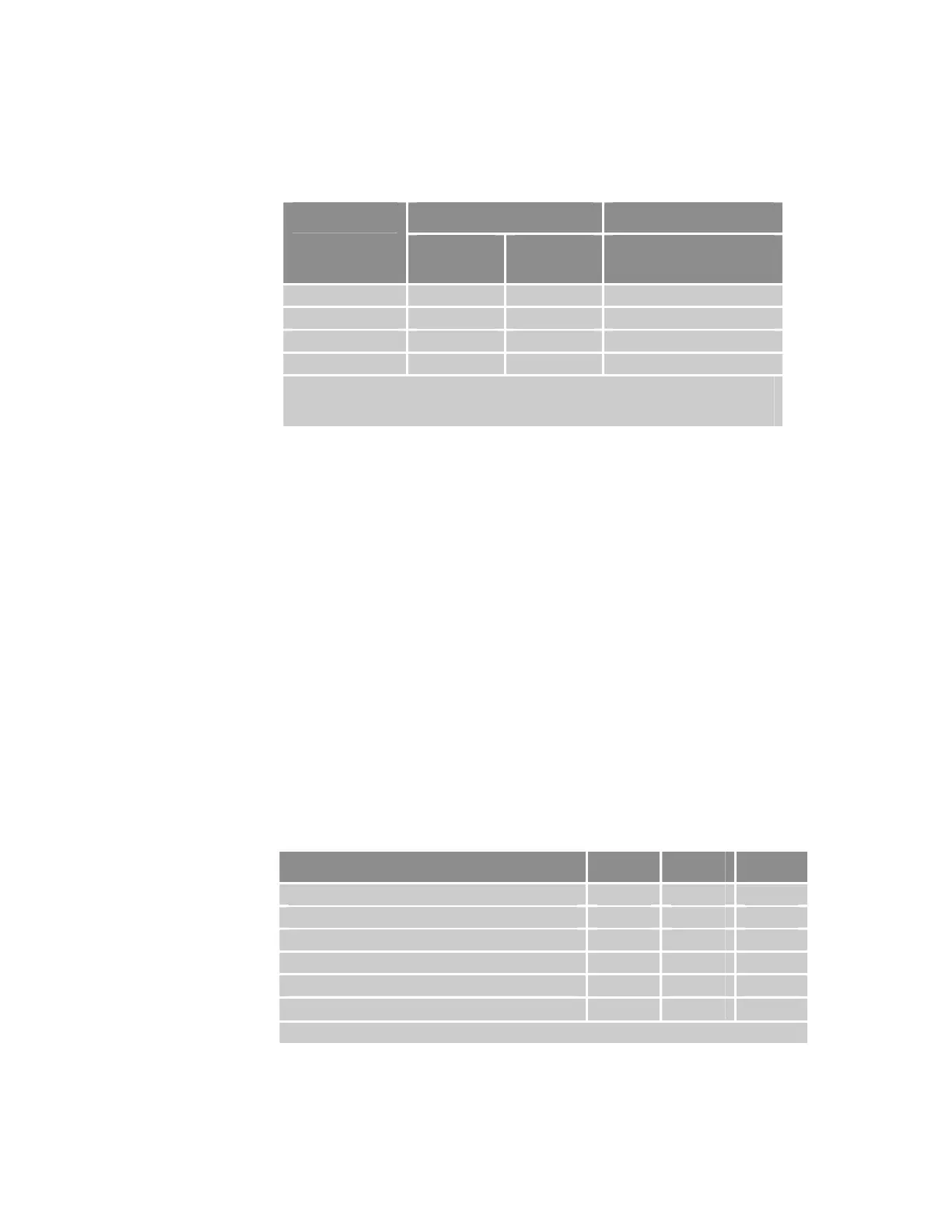
Table 19 summarizes signal assignments and supported features of the
encoder interface.
Axis Connector Signal Supported Features Mode
Encoder
CHA
Encoder
CHB
Position
Capture
1
Quadrature CHA CHB Yes
Step and Direction STEP DIR Yes
CW and CCW CW CCW Yes
SSI SCLK SDATA No
1. For more information on position capture, refer to the INTCAP command in the
ACR Command Language Reference (Online Help System in the ACR-View
software).
Table 19 Encoder Signal Assignments and Supported Features
Encoder Cable Disconnect
To improve reliability, the controller detects if the axis/encoder cable is
absent on a given axis by monitoring the Encoder CHA and Encoder CHB
signals. The feature does not distinguish between the causes, but identifies
which axis is experiencing the event. The controller does not monitor the
Encoder CHZ signal because the controller does not use it to close the servo
loop, and Encoder CHZ is not connected to an SSI device.
For more information on the encoder-cable-disconnect feature, refer to the
Encoder Flags section and “Bit Encoder Signal Lost” message in the ACR
Command Language Reference (Online Help System in the ACR-View
software).
Notes
• The encoder-cable-disconnect feature is not available for single-ended
encoders.
• For SSI devices, the controller monitors only the Encoder CHB signal.
Encoder Electrical/Timing Characteristics
Description Min Max Units
Pre-Quadrature frequency 0 5.0 MHz
Post-Quadrature frequency 0 20.0 MHz
Duty cycle (pre-quad frequency ≤ 2.5 MHz) 30 70 %
Duty cycle (pre-quad frequency > 2.5 MHz) 40 60 %
Receiver Differential Threshold, V
TH
−200
+200 mV
Common mode range, V
CM
−10
13.2 VDC
Note: All parameters are at the connector pin.
Table 20 Encoder Electrical/Timing Characteristics
Chapter 2 Specifications 45
www.comoso.com

 Loading...


