Parker Hannifin
Contacts .................................................. 30µ” Gold—AMP Part Number
748333-4
Gold Flash—Amp Part Number
748333-7
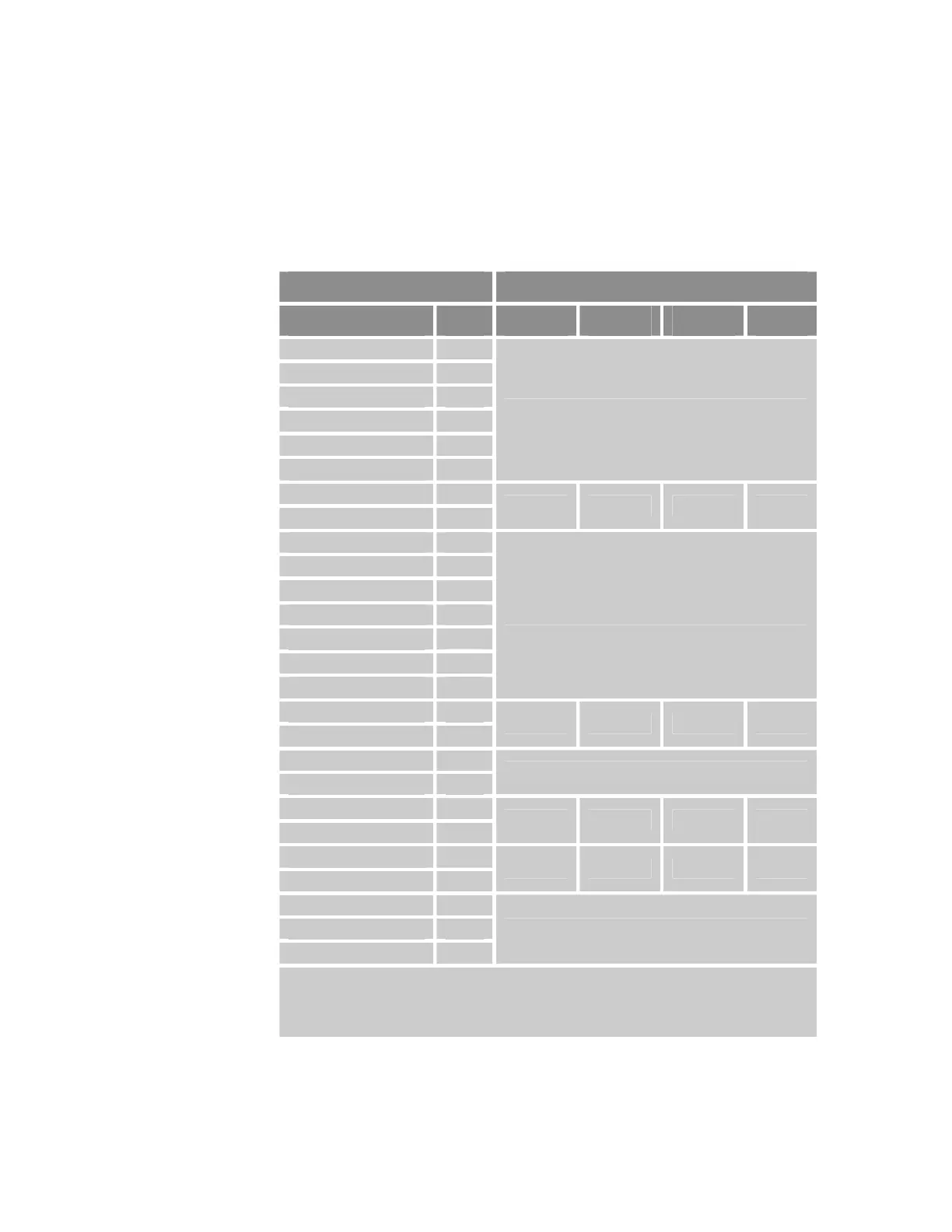
Axis Connector Pinout, Axis 0−3
Axis Connector AcroBASIC Direct I/O Reference
Signal Pin Axis 0 Axis 1 Axis 2 Axis 3
5 VDC PWR 1
DC RETURN 2
Encoder CHA+ 3
Encoder CHA−
4
Encoder CHB+ 5
Encoder CHB−
6
Not Applicable
Encoder CHZ+ 7
Encoder CHZ−
8
MRK 0 MRK 1 MRK 2 MRK 3
5VDC PWR 9
Drive Step+ 10
Drive Step−
11
Drive Direction+ 12
Drive Direction−
13
Drive AOUT+ 14
Drive AOUT−
15
Not Applicable
Drive Fault+ 16
Drive Fault−
17
INP 64 INP 65 INP 66 INP 67
5VDC PWR 18
Drive GND 19
Not Applicable
Drive Enable−
20
Drive Enable+ 21
OUT 40 OUT 41 OUT 42 OUT 43
Drive Reset−
22
Drive Reset+ 23
OUT 48 OUT 49 OUT 50 OUT 51
Drive GND 24
Drive Talk+ 25
Drive Talk−
26
Not Applicable
Note: If the Enable Drive I/O flag is set, then the AcroBASIC direct I/O commands can only
report the output status and cannot set or clear the output state.
The ACR9000 and ACR9030 controllers ship with a default state for all axes—
Enable Drive I/O flag set.
Table 10 Connector Pinout, Axes 0
−
3
Chapter 2 Specifications 35
www.comoso.com

 Loading...


