Parker Hannifin
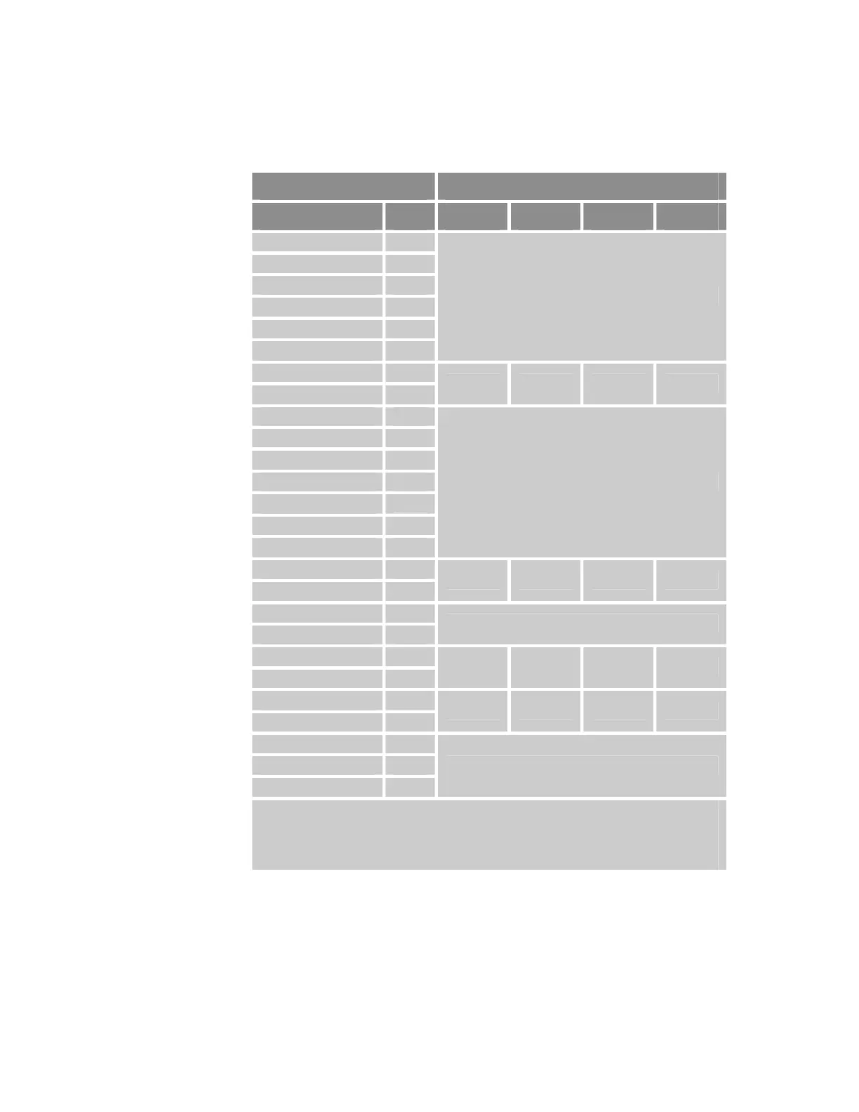
Axis Connector Pinout, Axis 4−7
Axis Connector AcroBASIC Direct I/O Reference
Signal Pin Axis 4 Axis 5 Axis 6 Axis 7
5 VDC PWR 1
DC RETURN 2
Encoder CHA+ 3
Encoder CHA−
4
Encoder CHB+ 5
Encoder CHB−
6
Not Applicable
Encoder CHZ+ 7
Encoder CHZ−
8
MRK 4 MRK 5 MRK 6 MRK 7
5VDC PWR 9
Drive Step+ 10
Drive Step−
11
Drive Direction+ 12
Drive Direction−
13
Drive AOUT+ 14
Drive AOUT−
15
Not Applicable
Drive Fault+ 16
Drive Fault−
17
INP 68 INP 69 INP 70 INP 71
5VDC PWR 18
Drive GND 19
Not Applicable
Drive Enable−
20
Drive Enable+ 21
OUT 44 OUT 45 OUT 46 OUT 47
Drive Reset−
22
Drive Reset+ 23
OUT 52 OUT 53 OUT 54 OUT 55
Drive GND 24
Drive Talk+ 25
Drive Talk−
26
Not Applicable
Note: If the Enable Drive I/O flag is set, then the AcroBASIC direct I/O commands can only
report the output status and not set or clear the output state.
The ACR9000 and ACR9030 controllers ship with a default state for all axes of—
Enable Drive I/O flag set.
Table 11 Connector Pinout, Axes 4
−
7
36 ACR9000 Series Hardware Installation Guide
www.comoso.com

 Loading...


