Parker Hannifin
Axis Connector Power Source
Each Axis (and Auxiliary Encoder) connector has a nominal +5 VDC power
source to aid application installations. The power source typically is used to
power:
• An external encoder, and
• Optical inputs and/or outputs between the ACR9000/ACR9030 and an
external drive.
Table 12 contains the electrical characteristics for the Axis-Connector power
source. Figure 1 provides a schematic of its circuit.
Description Min Max Units
Continuous current, +5V -- 150
1
mA
Trip current, +5V 700 1200 mA
Voltage tolerance from +5V (@ 150 mA or less) 4.9 5.5 VDC
1. Maximum current draw per Axis/Encoder Connector is 250 mA, not to exceed a combined
1500 mA for eight axis connectors and two auxiliary encoder connectors.
Note: All parameters are at the connector pin.
Table 12 Axis Power Electrical Characteristics
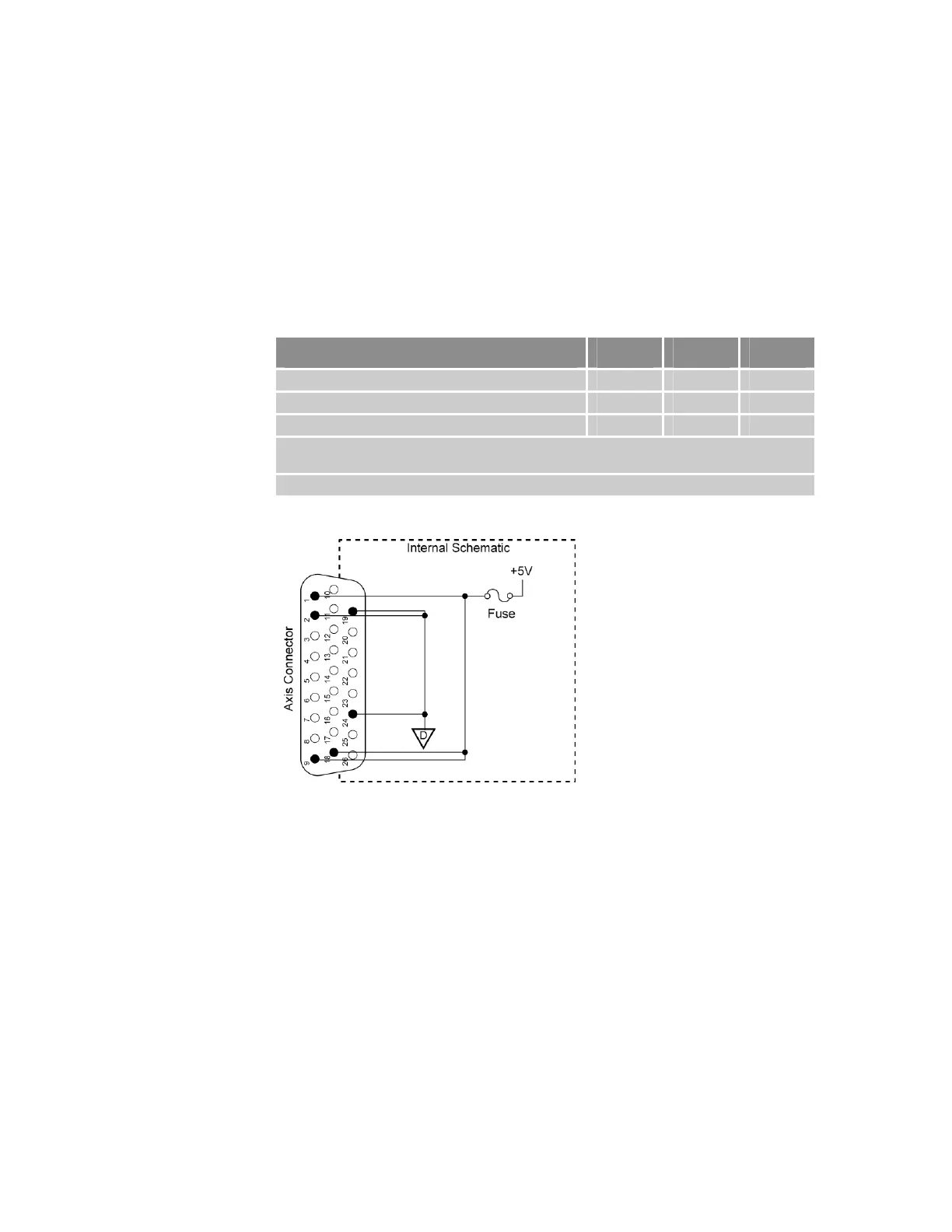
Figure 8 Equivalent Circuit for Axis Power Source
Axis-Connector Fuse
The Axis connector has a +5V voltage source for powering an encoder
and/or drive I/O, and includes a fuse, as shown in Figure 8 above. In the
event the +5V source shorts to ground, the internal reset-able fuse disables
the +5V source. When the short-circuit condition is removed and the fuse
cools, the fuse automatically resets.
Chapter 2 Specifications 37
www.comoso.com

 Loading...


