Parker Hannifin
Drive Electrical/Timing Characteristics
Table 15 through Table 18, on pages 40 and 41, contain the electrical
timing/characteristics for the following drive functions:
• Outputs—Drive Step and Drive Direction
• Outputs—Drive AOUT
• Inputs—Drive Fault
• Outputs—Drive Enable and Drive Reset
Important!
These electrical/timing characteristics only apply to the Axis connectors.
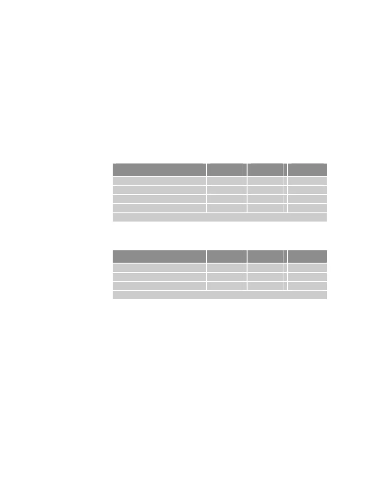
Outputs—Drive Step and Drive Direction
Description Min Max Units
Output voltage low at –30 mA -- 1 VDC
Output voltage high at +10 mA 3.7 --
Output voltage high at +30 mA 3.5 -- VDC
Step output frequency 0 2.5 MHz
Note: All parameters are at the connector pin.
Table 15 Outputs—Drive Step and Drive Direction Electrical/Timing Characteristics
Outputs—Drive AOUT
Description Min Max Units
Output voltage -10 +10 VDC
DAC resolution -- 16 bits
Load impedance 2k -- ohms
Note: All parameters are at the connector pin.
Table 16 Outputs—Drive AOUT Electrical/Timing Characteristics
40 ACR9000 Series Hardware Installation Guide
www.comoso.com

 Loading...


