Parker Hannifin
6. Noise induced on the Hall signals from routing the motor feedback cable
next to high-voltage cables (for example, strapped to motor power
cables).
Procedure 1—Motor Wires
Use this procedure to connect your motor wires to the drive.
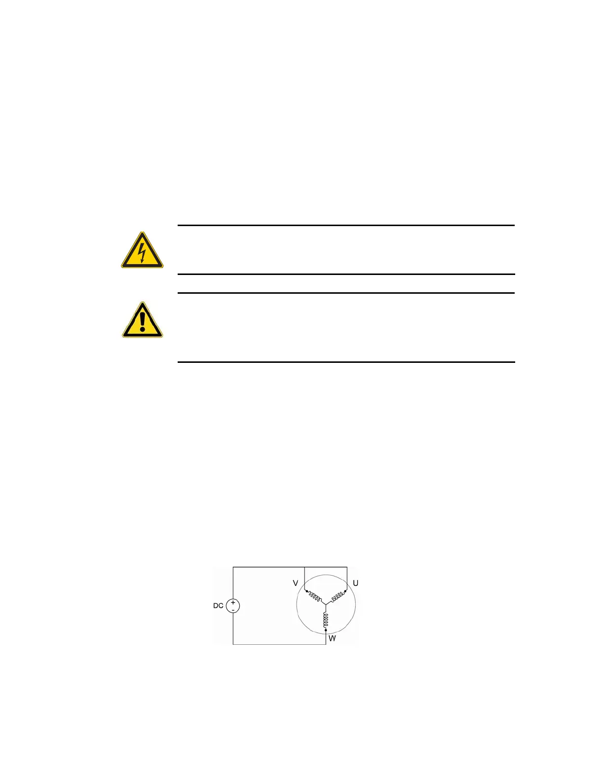
1. With the motor’s feedback cable connected to the drive, randomly
connect two motor power wires and slowly apply a positive voltage with
respect to the third. See Figure 49 on page 192.
Note: A variable low voltage (5 to 24V) current limiting (less than
continuous current rating of motor) power supply is preferred.
Warning — This procedure could damage the motor. Slowly increase the
voltage until the motor moves. Do not exceed the rated current.
Safety Warning — High-performance motion control equipment is capable
of producing rapid movement and very high forces. Unexpected motion may
occur especially during the development of controller programs.
KEEP
WELL CLEAR
of any machinery driven by stepper or servo motors. Never
touch any part of the equipment while it is in operation.
2. If
THALL reports a 1, 2, or 4, change SHALL from either 0 to 1 or from
1 to 0. After you change
SHALL, reset the drive.
3. Repeat step 1 until
THALL reports a value of 6.
4. The wire on the negative voltage or ground is motor wire W. The two
wires at the positive voltage are U and V.
Now there are two possibilities:
a. Connect the motor wires to the terminals. Operate the drive in
DMODE1. If the motor does not turn in the clockwise direction,
exchange motor wires U and V. Verify that the
CMDDIR command
is set to zero (Ø).
b. Put positive voltage on motor wire W together with either U or V
and put negative voltage or ground on the remaining wire. If
THALL reports a value of 3, the wire at the negative voltage is V. If
THALL reports a value of 5, the wire at the negative voltage is U.
Figure 49 Hall Connection Diagram
192 ACR9000 Series Hardware Installation Guide
www.comoso.com

 Loading...


