Parker Hannifin
GP Outputs 32−39
Description Min Typical Max Units
Turn-on time -- -- 2 ms
Turn-off time -- -- 1 ms
Working voltage -30
1
-- 30 VDC
On-Time voltage drop
(I
L
≤ 10 mA)
-- -- 0.4 VDC
On-time voltage drop
(10 mA < I
L
≤ 100 mA)
-- -- 4.0 VDC
Load current (T
A
≤ 35 °C) -- -- 100 mA
Load current, I
L
(35 °C < T
A
≤ 50 °C) -- -- 80 mA
Short-Circuit trip current -- 200 -- mA
1. The output is not polarity sensitivity, and can be controlled regardless of polarity.
Note: All parameters are at the connector pin.
Table 26 GP Outputs 32
−
39 Connector Electrical/Timing Characteristics
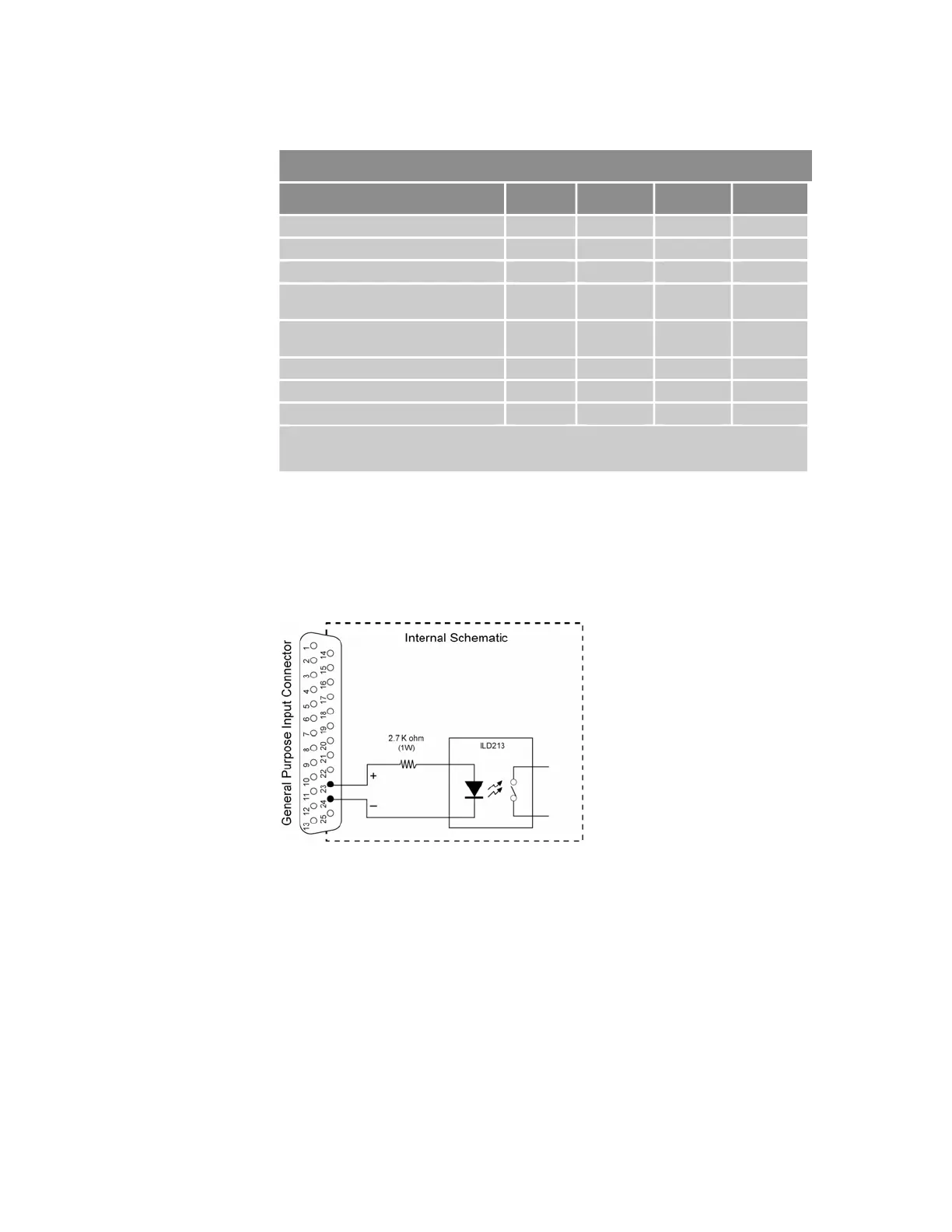
GP Input/Output Connector Circuit Schematics
This section contains schematics of the input and output circuits of the
ACR9000 and ACR9030 controllers. All inputs have the same circuit
schematic and all outputs have the same circuit schematic.
Figure 15 Equivalent Circuit for GP Inputs/Trigger Inputs Connector
Chapter 2 Specifications 51
www.comoso.com

 Loading...


