Setting Up the Detectors
4-90
Matching Detector Signals with Your Integrator
The following procedure should be followed if you are operating your detector near
the minimal detectable quantity level. This will ensure that the integrator is not
filtering the signal coming from the Clarus GC. The purpose of attenuation when an
integrator is attached and configured is to assure that the GC output is above the
noise level of the integrator.
Normally, attenuation for an integrator need only be performed once. To obtain the
most satisfactory results, it is recommended that attenuation be carried out under
actual operating conditions prior to running your first sample.
Valid attenuation values when an integrator is configured are 1, 2, 4, 8, 16, 32, and
64. The greater the attenuation, the smaller the degree of detector signal
amplification.
Attenuation of an integrator can be thought of as a two-step process:
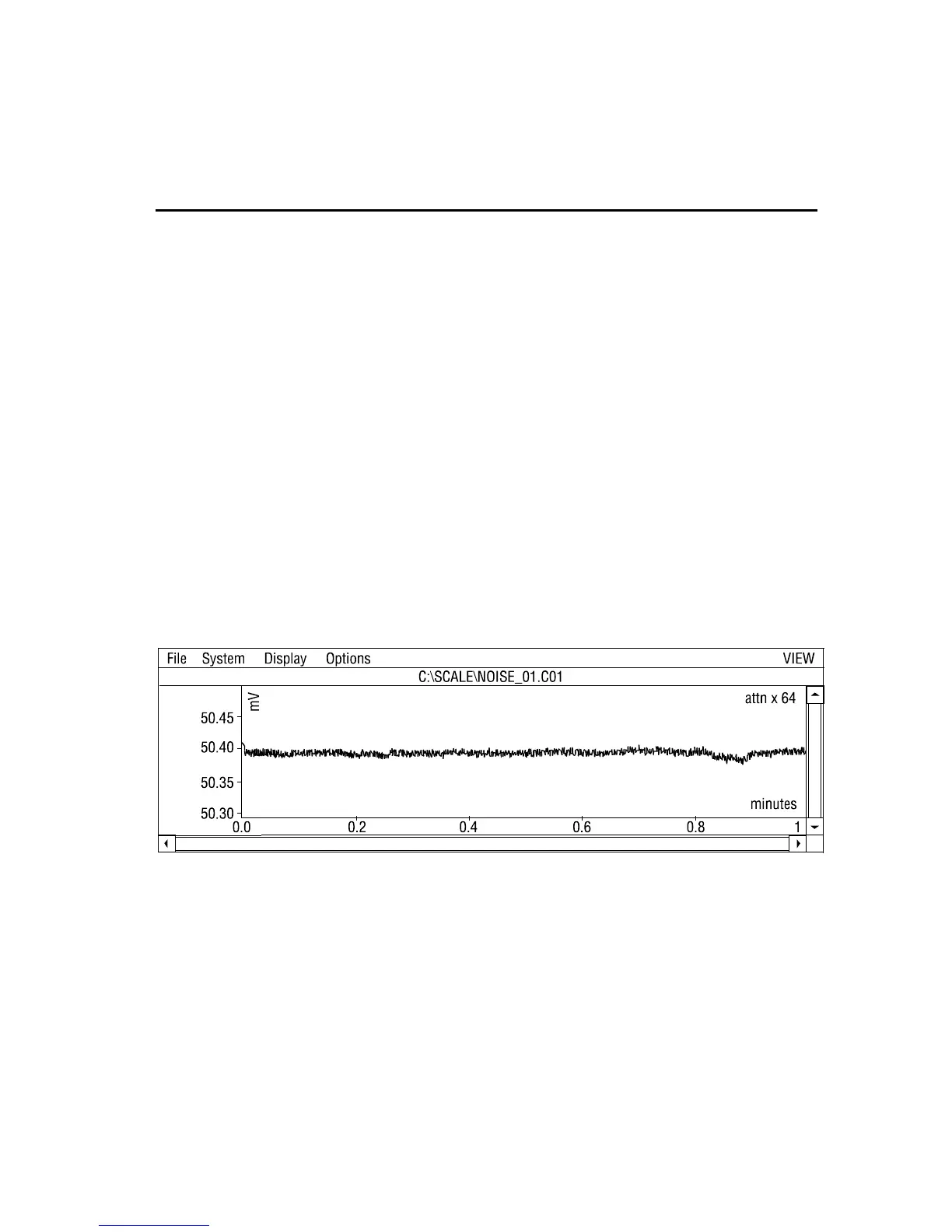
1. Observe the integrator noise at an attenuation of 64:
Figure 4-39. An example of integrator noise.
2. Gradually decrease the attenuation (for example, to 16 or until the noise level
increases):
 Loading...