Clarus 600/680 GC User’s Guide
6-35
Connecting the PPC Modules
The Clarus GC PPC modules have been properly installed and configured at the
factory for your specific combination of injectors and detectors. The configuration
information is stored in a reserved area of the battery-backed memory; however, if
the memory lost the PPC module connect configuration or if you installed a new
PPC module by purchasing an add-on kit, you must follow the procedure(s) listed
in this section.
By connecting a PCC module, you actually set the Clarus GC controlling software
to recognize a specific PPC module that is installed at a specific location. This is
necessary so that the software can control the installed hardware.
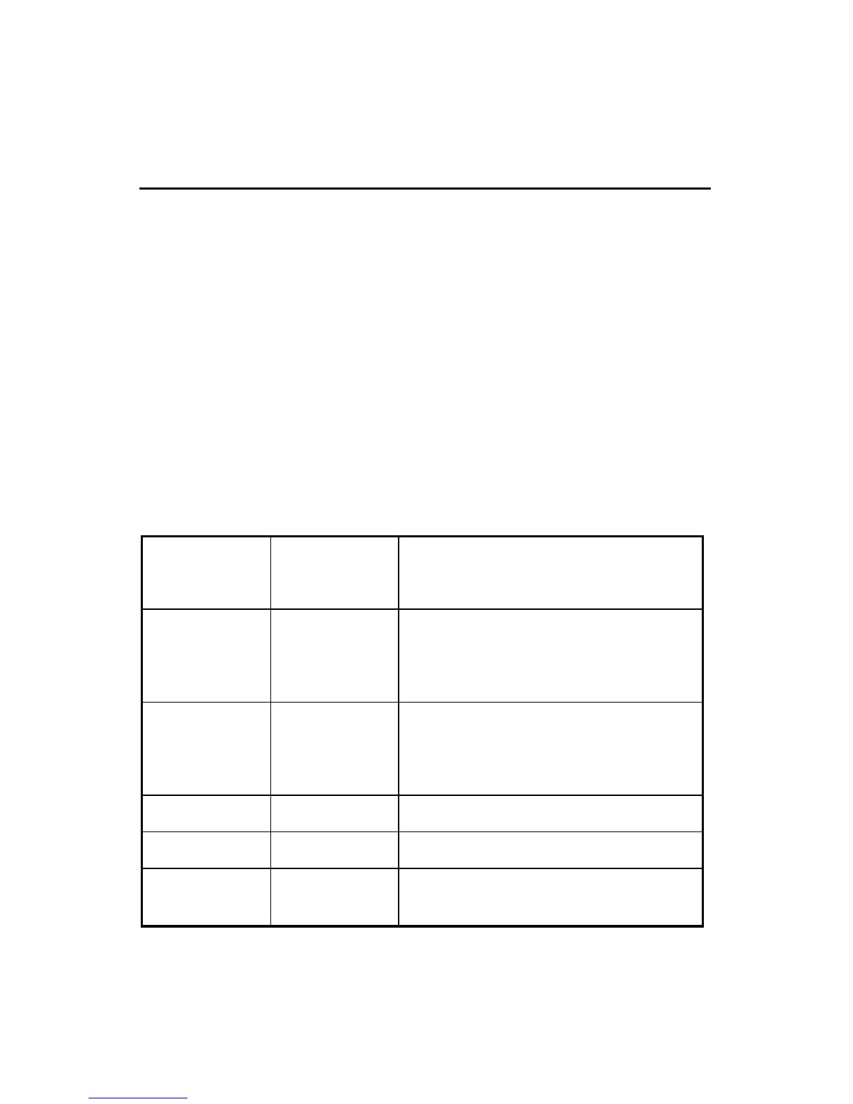
The PPC board has 12 sockets to which various injector and detector modules are
connected. The socket locations and descriptions are listed in the following table
and shown in the following figure:
Table 6-1. Injector and Detector Socket Descriptions
Injector 1
1 (J10)
Injector 2
2 (J11)
Injectors (Carriers)
Detector 1
Air or TCD Ref
3 (J12)
Detector 1
HYD or Make Up
4 (J13)
Detector 1
Detector 2
Air or TCD Ref
5 (J14)
Detector 2
HYD or Make Up
6 (J15)
Detector 2
7 (J16) 8 (J17)
Aux
9 (J18) 10 (J19)
11 (J20) 12 (J21)
Split Vent for CAP & PSS injectors or
Pressure Readout for PKD & POC injectors
 Loading...