R8C/20 Group, R8C/21 Group 14. Timers
Rev.2.00 Aug 27, 2008 Page 180 of 458
REJ09B0250-0200
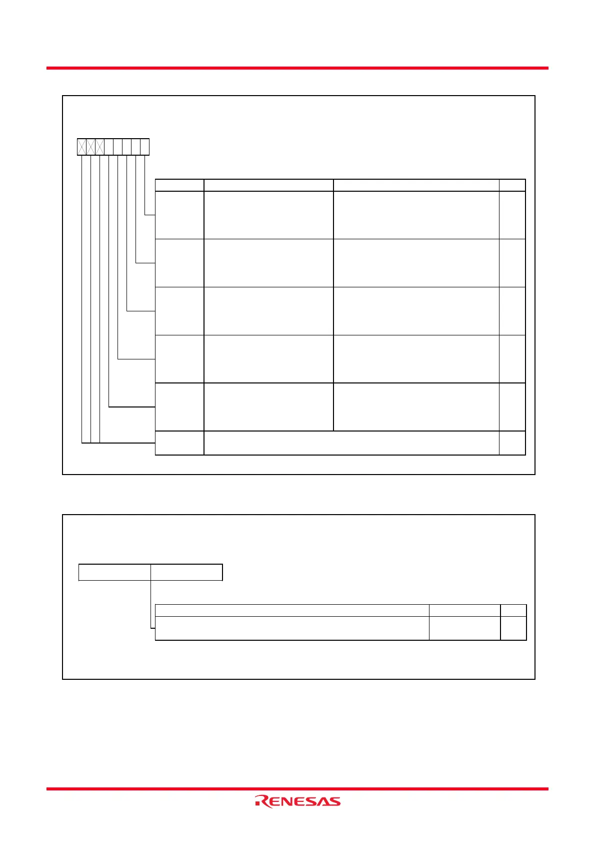
Figure 14.42 Registers TRDIER0 to TRDIER1 in Input Capture Function
Figure 14.43 Registers TRD0 to TRD1 in Input Capture Function
Timer RD Interrupt Enable Register i (i = 0 or 1)
Symbol Address After Reset
TRDIER0
TRDIER1
0144h
0154h
11100000b
11100000b
Bit Symbol Bit Name Function RW
b3 b2
IMIED
b1 b0b7 b6 b5 b4
RW
IMIEB RW
Input capture/compare match
interrupt enable bit A
0 : Disable an interrupt (IMIA) by the
IMFA bit
1 : Enable an interrupt (IMIA) by the
IMFA bit
Input capture/compare match
interrupt enable bit B
0 : Disable an interrupt (IMIB) by the
IMFB bit
1 : Enable an interrupt (IMIB) by the
IMFB bit
IMIEA
Input capture/compare match
interrupt enable bit C
0 : Disable an interrupt (IMIC) by the
IMFC bit
1 : Enable an interrupt (IMIC) by the
IMFC bit
IMIEC RW
RW
Input capture/compare match
interrupt enable bit D
0 : Disable an interrupt (IMID) by the
IMFD bit
1 : Enable an interrupt (IMID) by the
IMFD bit
Overflow/underflow interrupt
enable bit
0 : Disable an interrupt (OVI) by the
OVF bit
1 : Enable an interrupt (OVI) by the
OVF bit
RWOVIE
—
(b7 - b5)
—
Nothing is assigned. If necessary, set to 0.
When read, the content is 1.
Timer RD Counter i (i = 0 or 1)
(1)
Symbol Address After Reset
TRD0
TRD1
0147h-0146h
0157h-0156h
0000h
0000h
Setting Range RW
NOTE:
1.
(b8)
b0
(b15)
b7
Access the TRDi register in 16-bit units. Do not access it in 8-bit units.
b0b7
Function
Count a count source. Count operation is incremented.
When an overflow occurs, the OVF bit in the TRDSRi register is set to 1.
0000h to FFFFh RW
 Loading...