R8C/20 Group, R8C/21 Group 16. Clock Synchronous Serial Interface
Rev.2.00 Aug 27, 2008 Page 319 of 458
REJ09B0250-0200
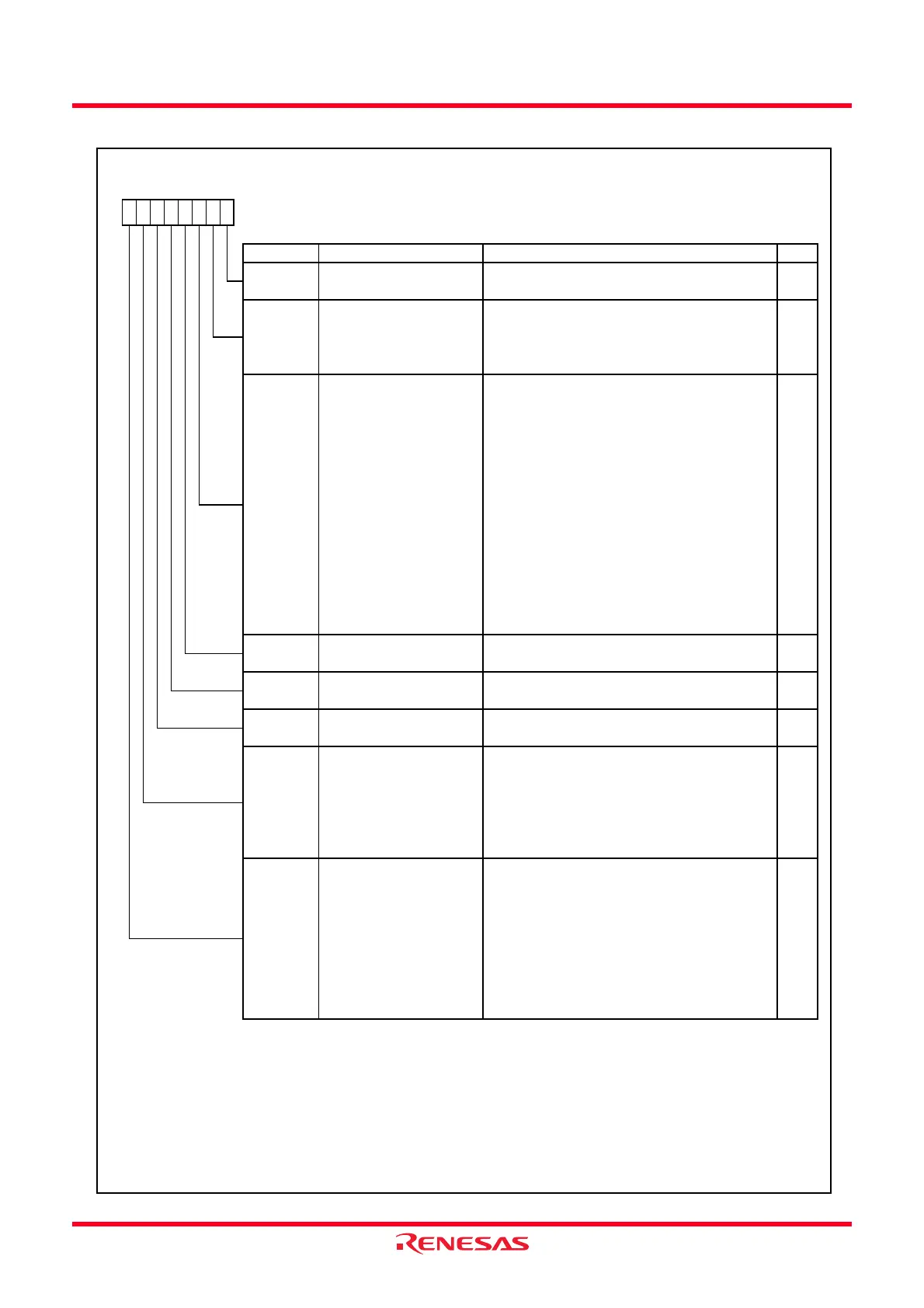
Figure 16.28 ICSR Register
IIC Bus Status Register
(7)
Symbol Address After Reset
ICSR
00BCh 0000X000b
Bit Symbol Bit Name Function RW
NOTES:
1.
2.
3.
4.
5.
6.
7.
STOP
Stop condition detection
flag
(1)
When the stop condition is detected after the frame
is transferred, this flag is set to 1
RW
The RDRF bit is set to 0 when reading data from the ICDRR register.
The TEND and TDRE bits are set to 0 when writing data to the ICDRT register.
When two or more master dev ices attempt to occupy the bus at nearly the same time, if the I
2
C bus Interf ace monitors the SDA pin
and the data which the IIC transmits is diff erent, the AL flag is set to 1 and the bus is occupied by the other masters.
RWRDRF
Receive data register full
(1,5)
When the 9th clock of the SCL signal w ith the I
2
C
bus format w hile the TDRE bit is set to 1, this flag is
set to 1
This flag is set to 1 w hen the final bit of the
transmit frame is transmitted w ith the clock
synchronous format
No acknow ledge detection
flag
(1,4)
This f lag is enabled in slave receive mode of the I
2
C bus format.
Each bit is set to 0 when reading 1 bef ore writing 0.
NACKF
When no acknow ledge is detected from receive
device w hen transmit, this flag is set to 1
RW
RW
When receive data is transferred from ICDRS to
ICDRR registers, this flag is set to 1
TEND
Transmit end
(1,6)
RW
RW
General call address
recognition flag
(1,2)
When detecting the general call address, this flag
is set to 1.
Arbitration lost flag /
overrun error flag
(1)
When the I
2
C bus format is used, this flag indicates
that arbitration is lost in master mode. In the
follow ing case, this flag is set to 1.
(3)
• When the internal SDA signal and SDA pin
level do not match at the rise of the SCL signal
in master transmit mode
• When the start condition is detected and the
SDA pin is held “H” in master transmit /
receive mode
This flag indicates that an overrun error occurs
w hen the clock synchronous format is used
In the following case, this flag is set to 1.
• When the last bit of the follow ing data is
received w hile the RDRF bit is set to 1
Slave address recognition
flag
(1)
This flag is set to 1 w hen the first frame follow ing
start condition matches the SVA0 to SVA6 bits in
the SAR register in slave receive mode. (Detect the
slave address and generate call address)
RWAAS
AL
ADZ
b2 b1b7 b6 b5 b4
When accessing the ICSR register continuously , insert one or more NOP instructions between the instructions to access it.
b0
The NACKF bit is enabled when the ACKE bit in the ICIER register is set to 1 (when the receiv e acknowledge bit is set to 1, transfer is
halted)
TDRE
Transmit data empty
(1,6)
In the following cases, this flag is set to 1
• Data is transferred from ICDRT to ICDRS
registers and ICDRT register is empty
• When setting the TRS bit in the ICCR1
register to 1 (transmit mode)
• When generating the start condition
(including retransmit)
• When changing from slave receive mode to
slave transmit mode
RW
b3
 Loading...