R8C/20 Group, R8C/21 Group 10. Clock Generation Circuit
Rev.2.00 Aug 27, 2008 Page 81 of 458
REJ09B0250-0200
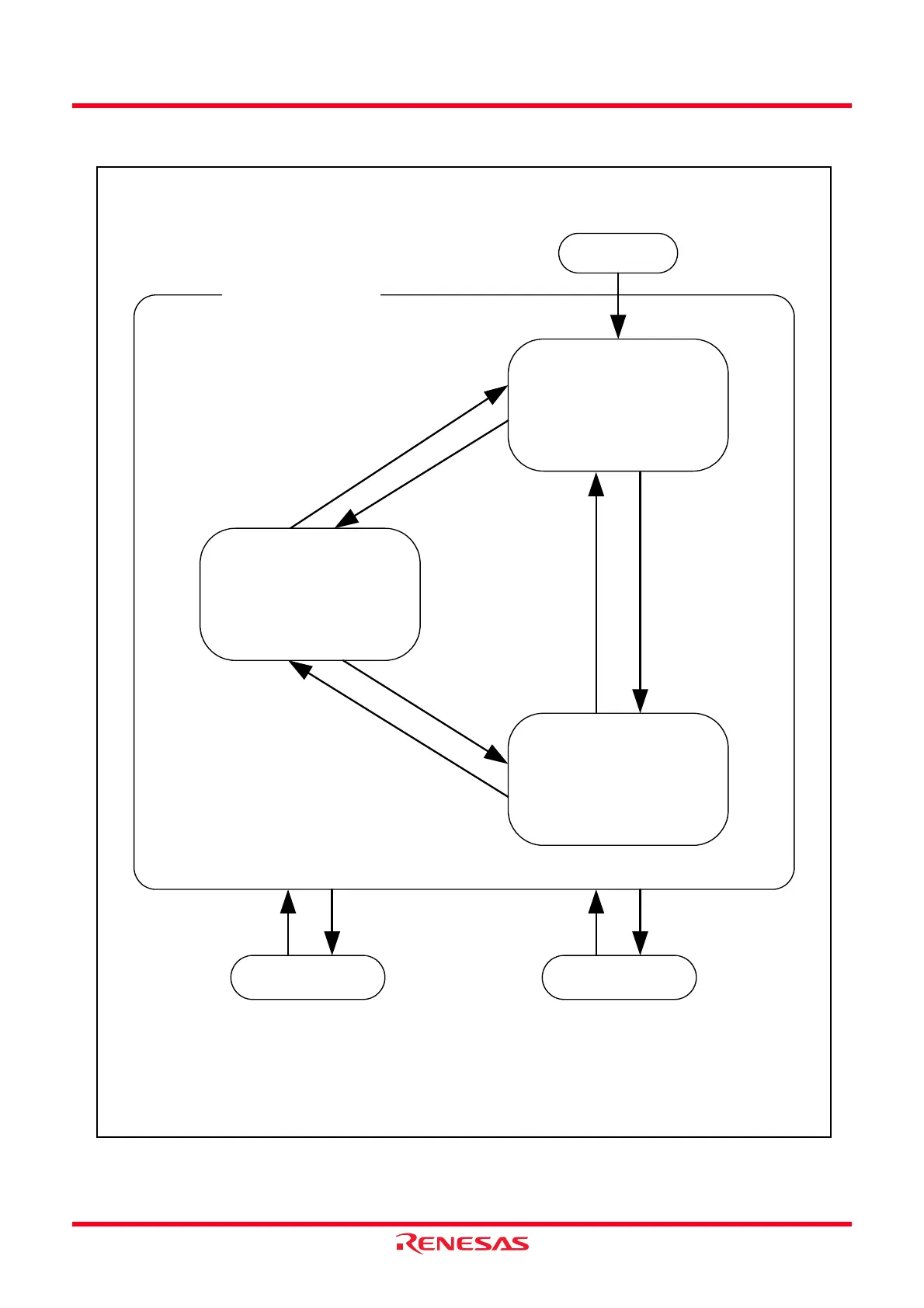
Figure 10.12 shows the State Transitions in Power Control Mode.
Figure 10.12 State Transitions in Power Control Mode
CM10 = 1
CPU operation stops
Stop mode
Reset
Wait mode
Low-speed on-chip oscillator mode
CM14 = 0
OCD2 = 1
FRA01 = 0
High-speed on-chip oscillator mode
OCD2 = 1
FRA00 = 1
FRA01 = 1
High-speed clock mode
CM05 = 0
CM13 = 1
OCD2 = 0
Standard operating mode
CM14 = 0
OCD2 = 1
FRA01 = 0
CM05 = 0
CM13 = 1
OCD2 = 0
CM05 = 0
CM13 = 1
OCD2 = 0
OCD2 = 1
FRA00 = 1
FRA01 = 1
FRA00 = 1
FRA01 = 1
CM14 = 0
FRA01 = 0
All oscillators stop
InterruptWAIT instruction
Interrupt
CM05 : CM0 register
CM13, CM14 : CM1 register
OCD2 : OCD register
FRA00, FRA01 : FRA0 register
State Transition in Power Control Mode
 Loading...