RL78/G10 CHAPTER 6 TIMER ARRAY UNIT
R01UH0384EJ0311 Rev. 3.11 148
Dec 22, 2016
6.6.2 TO0n pin output setting
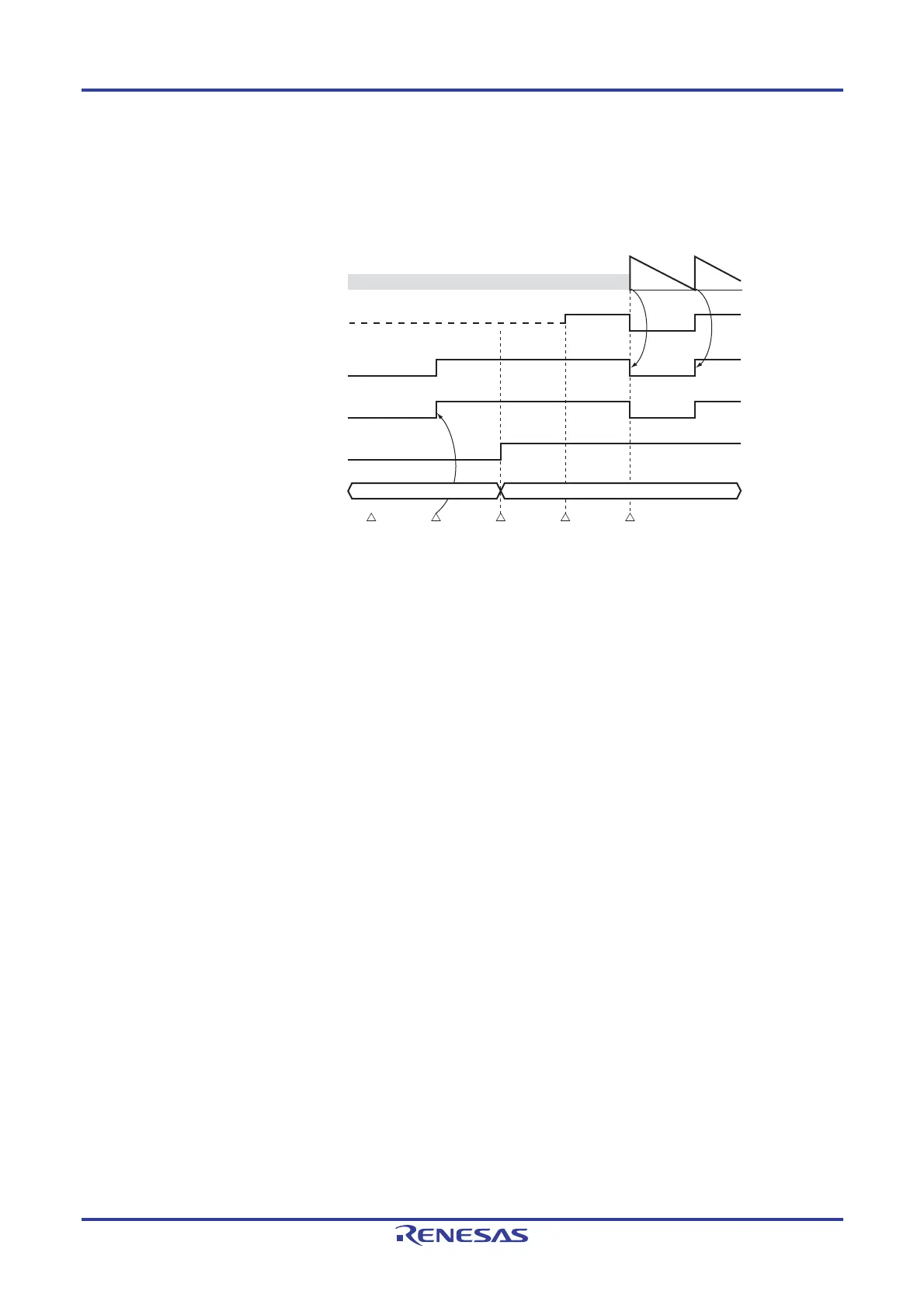
The following figure shows the procedure and status transition of the TO0n output pin from initial setting to timer
operation start.
Figure 6-30. Status Transition from Timer Output Setting to Operation Start
TCR0n
Timer alternate-function pin
Timer output signal
TOE0n
T
O0n
(Counter)
Undefined value (FFFFH after reset)
Write operation enabled period to TO0n
<1> Set TOM0n
Set TOL0n
<4> Set PMC0,
PMx, and Px
<2> Set TO0n <3> Set TOE0n <5> Timer operation start
Write operation disabled period to TO0n
Hi-Z
<1> The operation mode of timer output is set.
• TOM0n bit (0: Master channel output mode, 1: Slave channel output mode)
• TOL0n bit (0: Positive logic output, 1: Negative logic output)
<2> The timer output signal is set to the initial status by setting timer output register 0 (TO0).
<3> The timer output operation is enabled by writing 1 to the TOE0n bit (writing to the TO0 register is disabled).
<4> The port is set to digital I/O by the port mode control register (PMC0). The port is set to output mode by the
port mode register (PM0). The output latch for the port is set to 0 by the port register (P0) (see 6.3.14
Registers controlling port functions of pins to be used for timer I/O).
<5> The timer operation is enabled (TS0n = 1).
Remark n: Channel number
n = 0, 1 (for 10-pin products); n = 0 to 3 (for 16-pin products)

 Loading...


