RL78/G10 APPENDIX A REVISION HISTORY
R01UH0384EJ0311 Rev. 3.11 609
Dec 22, 2016
A.2 Revision History of Preceding Editions
Here is the revision history of the preceding editions. Chapter indicates the chapter of each edition.
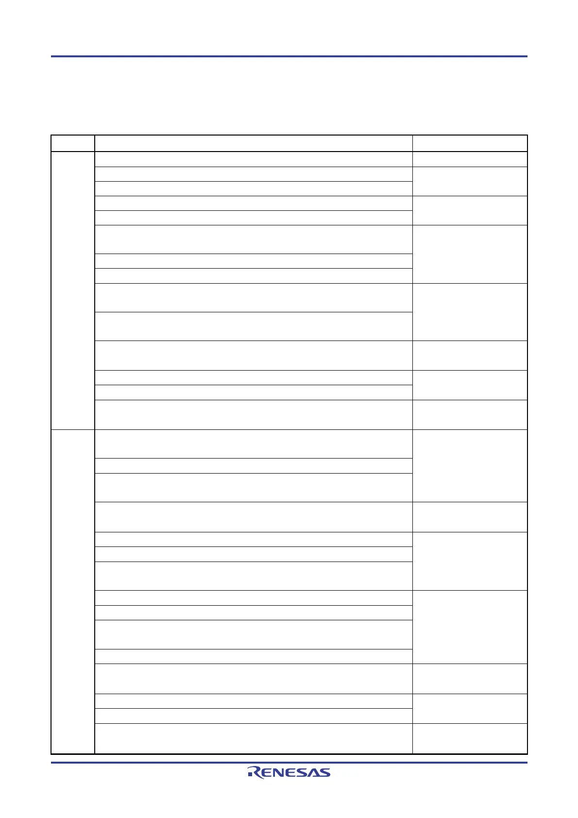
(1/9)
Edition
Description Chapter
Rev.3.10
Deletion of under development
Throughout
Corrected Table 1-1. List of Ordering Part Numbers
CHAPTER 1 OUTLINE
Modification of 1.3 Pin Configuration (Top View)
Addition of Caution to Figure 2-5. Pin Block Diagram for Pin Type 7-1-2
CHAPTER 2 PIN FUNCTIONS
Addition of Caution to Figure 2-7. Pin Block Diagram for Pin Type 7-3-2
Addition of description to Figure 5-4. Format of Clock Operation Status Control
Register (CSC)
CHAPTER 5 CLOCK
GENERATOR
Modification of Table 5-4. Changing CPU Clock
Addition of description to 5.6.6 Conditions before clock oscillation is stopped
Addition of description to 6.4.2 Basic rules of 8-bit timer operation function (only
channels 1 and 3)
CHAPTER 6 TIMER ARRAY
UNIT
Corrected Note of Figure 6-77. Example of Set Contents of Registers for PWM Output
Function (Slave Channel) (1/2)
Corrected Figure 10-17. Overall Error to Figure 10-22. Differential Linearity Error
CHAPTER 10 A/D
CONVERTER
Addition of description to 13.3.6 IICA low-level width setting register 0 (IICWL0)
CHAPTER 13 SERIAL
INTERFACE IICA
Corrected 13. 5. 17 (1) (c) (ii) When WTIM0 = 1
Corrected Caution 2 of Figure 14-3. Format of Interrupt Request Flag Registers
(IF0L, IF0H, IF1L) (16-pin product)
CHAPTER 14 INTERRUPT
FUNCTIONS
Rev.3.00
Addition of industrial applications in Figure 1-1 Part Number, Memory Size, and
Package of RL78/G10
CHAPTER 1
OUTLINE
Addition of industrial applications in Table 1-1 List of Ordering Part Numbers
Addition of description to pin configuration in 1.3.1 10-pin products and 1.3.2 16-pin
products
Addition of 5.7 Resonator and Oscillator Constants
CHAPTER 5 CLOCK
GENERATOR
Addition of figure in 12.2.1 Shift register
CHAPTER 12 SERIAL
ARRAY UNIT
Modification of caution in Figure 12-14 Format of Serial Output Register 0 (SO0)
Modification of caution in Figure 12-15 Format of Serial Clock Output Register 0
(CKO0)
Addition of description in Figure 13-27 Master Operation in Single-Master System
CHAPTER 13 SERIAL
INTERFACE IICA
Addition of description in Figure 13-28 Master Operation in Multi-Master System (1/3)
Modification of description in Figure 13-28 Master Operation in Multi-Master System
(2/3)
Addition of description in Figure 13-29 Slave Operation Flowchart (1)
Addition of description and remark 1 in 20.3.1 P40/TOOL0 pin
CHAPTER 20 FLASH
MEMORY
Correction of error in 24.5.1 (3) CSI mode (slave mode, SCKp... external clock input)
CHAPTER 24 ELECTRICAL
SPECIFICATIONS
Renamed to 24.7 RAM Data Retention Characteristics and modification of figure
Addition of industrial application in 25.1 10-pin products
CHAPTER 25 PACKAGE
DRAWINGS

 Loading...


