RL78/G10 CHAPTER 12 SERIAL ARRAY UNIT
R01UH0384EJ0311 Rev. 3.11 399
Dec 22, 2016
12.7.3 Data reception
Data reception is an operation to receive data to the target for transfer (slave) after transmission of an address field.
After all data are received to the slave, a stop condition is generated and the bus is released.
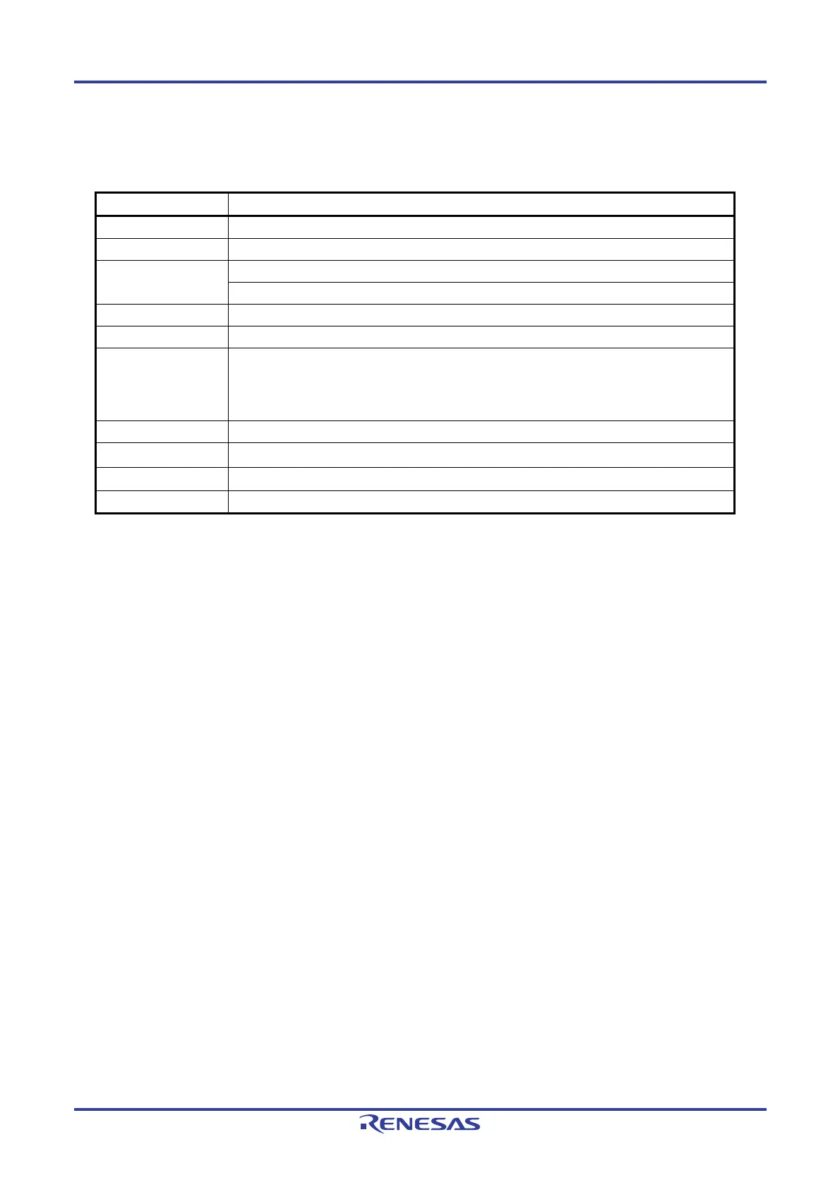
Simplified I
2
C IIC00
Target channel Channel 0 of SAU0
Pins used SCL00, SDA00
Note 1
Interrupt INTIIC00
Transfer end interrupt only (Setting the buffer empty interrupt is prohibited.)
Error detection flag Overrun error detection flag (OVF0n) only
Transfer data length 8 bits
Transfer rate
Note 2
Max. f
MCK/4 [Hz] (SDR0nH[7:1] = 1 or more) fMCK: Operation clock frequency of target channel
However, the following condition must be satisfied in each mode of I
2
C.
• Max. 400 kHz (fast mode)
• Max. 100 kHz (standard mode)
Data level Non-inversion output (default: high level)
Parity bit No parity bit
Stop bit Appending 1 bit (ACK transmission)
Data direction MSB first
Notes 1. To perform communication via simplified I
2
C, set the N-ch open-drain output (VDD tolerance) mode (POM01
= 1) for the port output mode register (POM0) (see 4.3 Registers Controlling Port Function for details).
2. Use this operation within a range that satisfies the conditions above and the peripheral function
characteristics in the electrical specifications (see CHAPTER 24 ELECTRICAL SPECIFICATIONS).
Remark n = 0

 Loading...


