RL78/G10 CHAPTER 11 COMPARATOR
R01UH0384EJ0311 Rev. 3.11 273
Dec 22, 2016
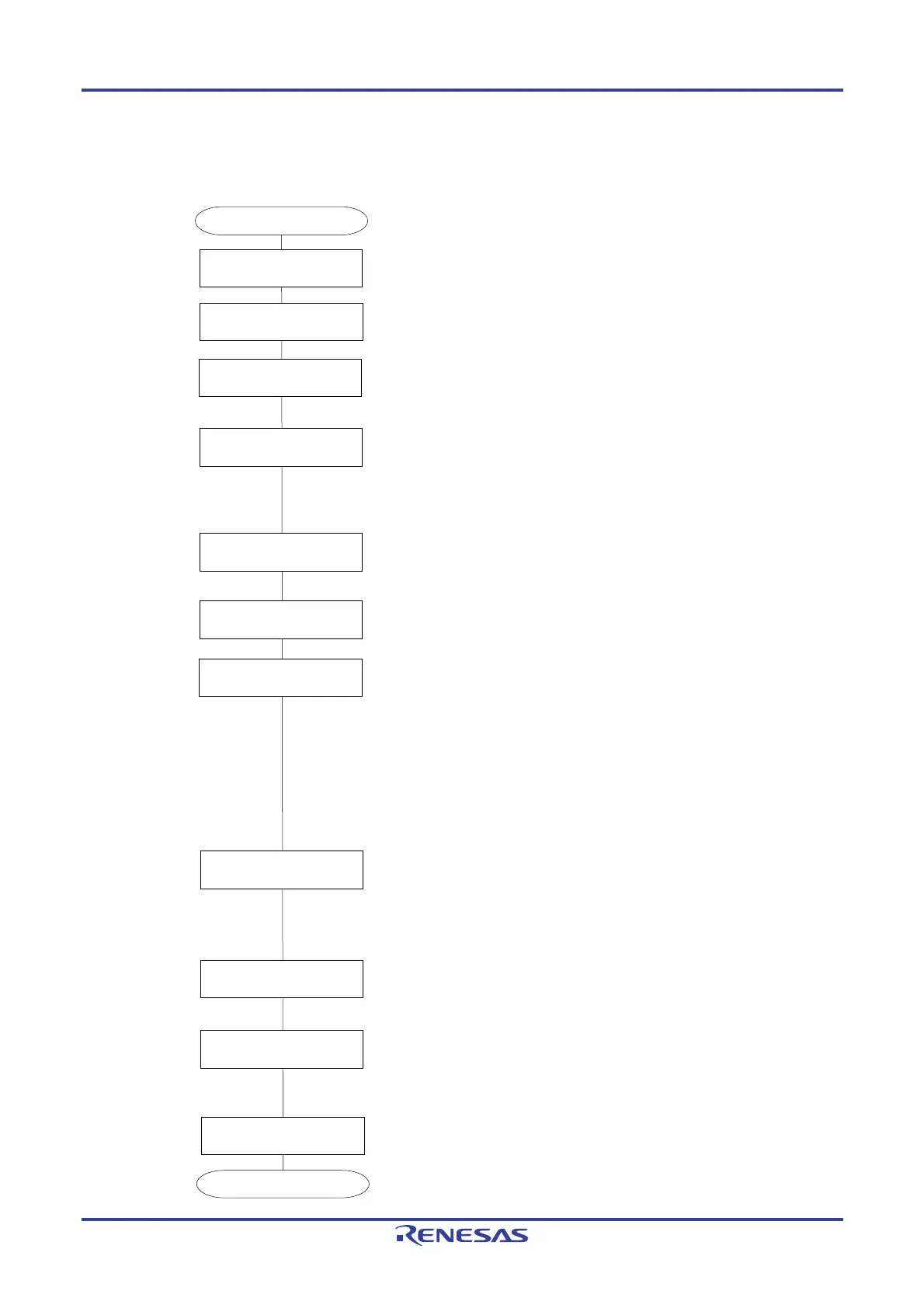
11.5.1 Enabling Comparator Operation
Figure 11-8. Procedure for Enabling Comparator Operation
Start
Set PER0 register.
Set bit CMPEN in PER0 to 1 to supply clock to comparator.
Specify comparator response speed.
•
Set bit SPDMD in COMPOCR to 1: High-speed mode
•
Clear bit SPDMD in COMPOCR to 0: Low-speed mode
Set the ports for IVCMP0 and IVREF0 pins to analog input
function.
• Set
bits in PMC0 and PM0 to 1.
Set PMC0 and PM0 registers
Set C0VRF bit.
Set SPDMD
bit.
Set C0ENB bit.
Wait for comparator stabilization.
Set COMPFIR register.
Enable or disable the digital filter of the comparator and set the
effective edge for an interrupt.
•
Set bits C0FCK1 and C0FCK0 in COMPFIR:
00B: Digital filter disabled
01B: Digital filter enabled, sampling clock:
fCLK
10B: Digital filter enabled, sampling clock:
fCLK/8
11B: Digital filter enabled, sampling clock:
fCLK/32
•
Set bits C0EPO and C0EDG in COMPFIR:
00B: Rising edge
01B: Falling edge
1xB: Both rising and falling edges
Set C0OP and C0OE bits
Output comparator comparison result from VCOUT0 pin.
•
Set bit C0OP in COMPOCR:
0B:
Non-inverted comparator result is output from VCOUT0 pin.
1B:
Inverted comparator result is output from VCOUT0 pin.
•
Set
bit C0OE in COMPOCR to 1 to enable output.
•
Set the port for VCOUT0 pin to output function.
Set bits in PMC0 and PM0 to 1.
Set bits in P0 to 1.
Specify VCOUT0 pin as output.
Specify interrupt (INTCMP0).
Set C0IE bit.
End
Specify the comparator interrupt.
•
Specify the interrupt priority level by bits CMPPR00 and
CMPPR10 in PR1L.
•
Initialize interrupt request by clearing bit CMPIF0 in IF1L to 0.
•
Enable vector interrupt by clearing bit CMPMK0 in MK1L to 0.
•
Enable interrupt request by setting bit C0IE in COMPOCR to 1.
(Mandatory)
(Mandatory)
(Mandatory)
(Mandatory)
(Mandatory)
(Mandatory)
(Optional)
(Optional)
(Optional)
(Optional)
(Optional)
Enable the comparator operation.
• Set bit C0ENB in COMPMDR to 1 to enable comparator
0 operation.
Specify comparator reference voltage.
•
Set bit C0VRF in COMPMDR to 1
:
Supplied from internal
reference voltage (0.815 V (typ.))
•
Clear bit C0VRF in COMPMDR to 0: Supplied from IVREF0 pin
Count the comparator output stabilization signals (t
CMP
).
For information on tCMP,
refer to
24.6.2 Comparator characteristics.
 Loading...


