RL78/G10 CHAPTER 11 COMPARATOR
R01UH0384EJ0311 Rev. 3.11 272
Dec 22, 2016
11.4.1 Comparator 0 Digital Filter Operation
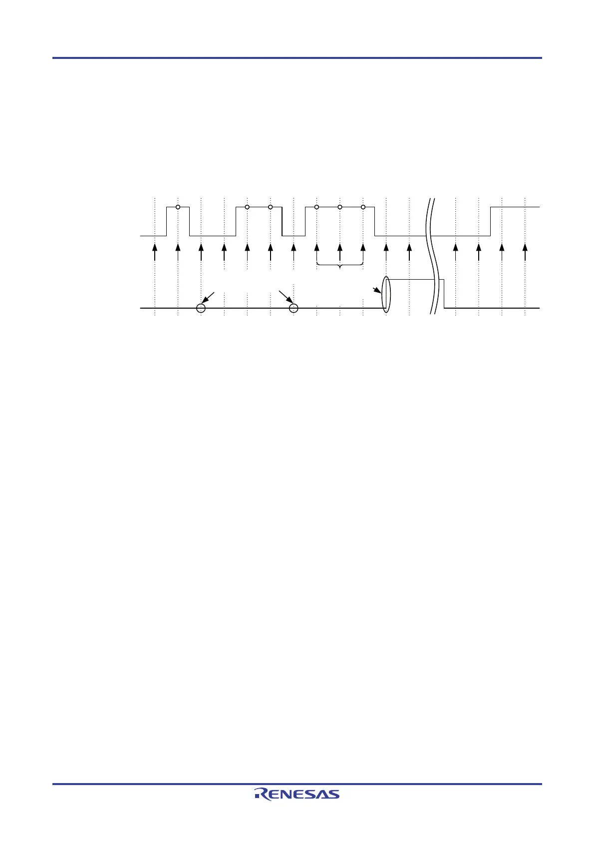
Comparator 0 incorporates a digital filter. The sampling clock is selected by bits C0FCK1 and C0FCK0 in the COMPFIR
register. The comparator 0 output signal is sampled every sampling clock, and when the level of the output signal matches
three times, the digital filter output changes at the next sampling clock.
Figure 11-7 shows the comparator 0 digital filter and interrupt operation example.
Figure 11-7. Comparator 0 Digital Filter and Interrupt Operation Example
C0MON
Sampling timing
Comparator 0 interrupt
(INTCMP0)
Since the level
matched three times, it
is recognized as signal
change and bit CMPIF0
is set to 1.
If the level does not match three
times, it is assumed to be noise and
bit CMPIF0 does not change.
Remark The operation example in Figure 11-7 applies when the digital filter is enabled (bits C0FCK1 and C0FCK0 in
the COMPFIR register is 01B, 10B, or 11B).
11.4.2 Comparator 0 Interrupt Operation
When using the comparator 0 interrupt, set the C0IE bit in the COMPOCR register to 1 (interrupt request enabled). The
condition for interrupt request generation can be set by the COMPFIR register. The comparator outputs can also be
passed through the digital filter.
For details on the register setting, refer to 11.3.3 Comparator Filter Control Register (COMPFIR) and 11.3.4
Comparator Output Control Register (COMPOCR).
11.4.3 Comparator 0 Output
The comparison result from the comparator can be output from the VCOUT0 pin. Bits C0OP and C0OE in the
COMPOCR register are used to set the output polarity (inverted or non-inverted output) of the VCOUT0 pin and enable or
disable the VCOUT0 pin output, respectively. For details on the register settings, refer to 11.3.4 Comparator Output
Control Register (COMPOCR).
To output the comparator comparison result from the VCOUT0 pin, follow the procedure shown in Figure 11-8,
Procedure for Enabling Comparator Operation.
11.5 Comparator Setting Flowchart
Figure 11-8 shows the comparator setting flowchart.

 Loading...


