RL78/G10 CHAPTER 9 WATCHDOG TIMER
R01UH0384EJ0311 Rev. 3.11 236
Dec 22, 2016
9.2 Configuration of Watchdog Timer
The watchdog timer includes the following hardware.
Table 9-1. Configuration of Watchdog Timer
Item Configuration
Control register Watchdog timer enable register (WDTE)
How the counter operation is controlled and overflow time are set by the option byte.
Table 9-2. Setting of Option Bytes and Watchdog Timer
Setting of Watchdog Timer Option Byte (000C0H)
Controlling counter operation of watchdog timer Bit 4 (WDTON)
Overflow time of watchdog timer Bits 3 to 1 (WDCS2 to WDCS0)
Controlling counter operation of watchdog timer
(in HALT/STOP mode)
Bit 0 (WDSTBYON)
Remark For the option byte, see CHAPTER 19 OPTION BYTE.
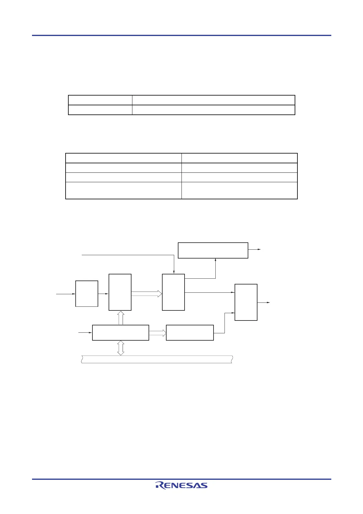
Figure 9-1. Block Diagram of Watchdog Timer
Clock
input
controller
Reset
output
controller
Internal reset signal
Internal bus
Interval interrupt request signal
(INTWDTI)
Interval time controller
(2
n
/f
IL
× 0.75)
Selector
17-bit
counter
Watchdog timer enable
register (WDTE)
WDTON of option
byte (000C0H)
WDCS2 to WDCS0 of
option byte (000C0H)
Overflow signal
Write detector to
WDTE except ACH
f
IL
(2
6
-1)/f
IL
to
(2
16
-1)/f
IL

 Loading...


