RL78/G10 CHAPTER 18 SELECTABLE POWER-ON-RESET CIRCUIT
R01UH0384EJ0311 Rev. 3.11 541
Dec 22, 2016
CHAPTER 18 SELECTABLE POWER-ON-RESET CIRCUIT
18.1 Functions of Selectable Power-on-reset Circuit
The selectable power-on-reset (SPOR) circuit has the following functions.
• Generates internal reset signal at power on.
The reset signal is released when the supply voltage exceeds the detection voltage (V
DD ≥ VSPOR).
• The SPOR circuit compares the supply voltage (V
DD) with the detection voltage (VSPDR), and generates an internal
reset signal when VDD < VSPDR.
• The detection level for the power supply detection voltage (V
SPOR, VSPDR) can be selected by using the option byte
(000C1H) as one of 4 levels (for details, see 19.2 Format of User Option Byte).
Bit 0 (SPORF) of the reset control flag register (RESF) is set to 1 if reset occurs. For details of the RESF register, see
CHAPTER 17 RESET FUNCTION.
Note The values of all flags in the reset control flag register (RESF) are retained until VDD reaches data retention
lower limit voltage.
Remark V
SPOR: SPOR power supply rise detection voltage
VSPDR: SPOR power supply fall detection voltage
For details, see 24.6.4 SPOR circuit characteristics.
18.2 Configuration of Selectable Power-on-reset Circuit
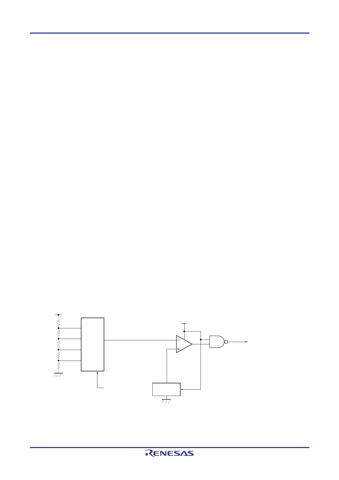
The block diagram of the selectable power-on-reset circuit is shown in Figure 18-1.
Figure 18-1. Block Diagram of Selectable Power-on-reset Circuit
Internal reset signal
Option byte (000C1H)
SPORS1, SPORS0
Voltage detection level
selector
VDD
VDD
Reference
voltage source

 Loading...


