RL78/G10 CHAPTER 11 COMPARATOR
R01UH0384EJ0311 Rev. 3.11 270
Dec 22, 2016
11.3.4 Comparator Output Control Register (COMPOCR)
This register selects the comparator response speed, controls the VCOUT0 output, and enables or disables the
interrupt request signal.
The COMPOCR register can be set by a 1-bit or 8-bit memory manipulation instruction.
Reset signal generation clears this register to 00H.
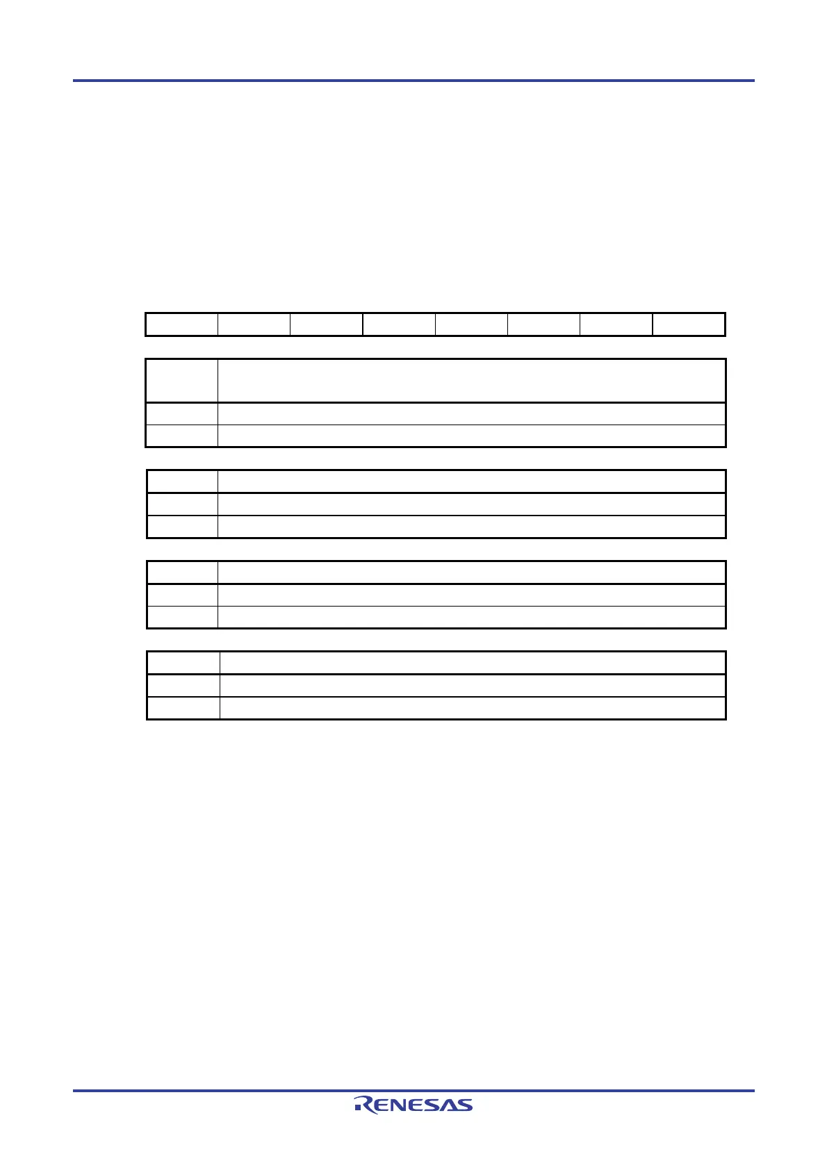
Figure 11-5. Format of Comparator Output Control Register (COMPOCR)
Address: FFF62H After reset: 00H R/W
Symbol <7> 6 5 4 3 <2> <1> <0>
COMPOCR SPDMD 0 0 0 0 C0OP C0OE C0IE
SPDMD
Note 1
Comparator speed selection
0 Low-speed mode
1 High-speed mode
C0OP VCOUT0 output polarity selection
0 Non-inverted comparator 0 output is output from the VCOUT0 pin.
1 Inverted comparator 0 output is output from the VCOUT0 pin.
C0OE VCOUT0 pin output enable/disable
0 Comparator 0 VCOUT0 pin output disabled
1 Comparator 0 VCOUT0 pin output enabled
C0IE Comparator 0 interrupt request enable/disable
0 Comparator 0 interrupt request disabled
1 Comparator 0 interrupt request enabled
Note When rewriting the SPDMD bit, be sure to clear the C0ENB bit in the COMPMDR register to 0 in
advance.
11.3.5 Registers Controlling Port Functions of Comparator I/O Pins
The port mode register (PM0), the port register (P0), and the port mode control register (PMC0) should be appropriately
set to control the functions of the port pins that are also used for input and output of the comparator. For details, refer to
4.3.1 Port mode registers 0, 4 (PM0, PM4), 4.3.2 Port registers 0, 4, 12, 13 (P0, P4, P12, P13), and 4.3.5 Port mode
control register 0 (PMC0). For an example of settings when using a port pin for input and output of the comparator, see
4.5.3 Example of register settings for port and alternate functions used.
When using the IVCMP0 and IVREF0 pins as analog inputs of the comparator, the appropriate bits should be set to 1 in
the port mode register (PM0) and the port mode control register (PMC0) that correspond to each port.
When using the VCOUT0 pin as a comparator output, bits should be cleared to 0 in the port mode register (PM0), the
port register (P0) and the port mode control register (PMC0). For details on the VCOUT0 pin setting, follow the setting
procedure in 11.4.3 Comparator 0 Output.

 Loading...


