RL78/G13 CHAPTER 12 SERIAL ARRAY UNIT
R01UH0146EJ0100 Rev.1.00 632
Sep 22, 2011
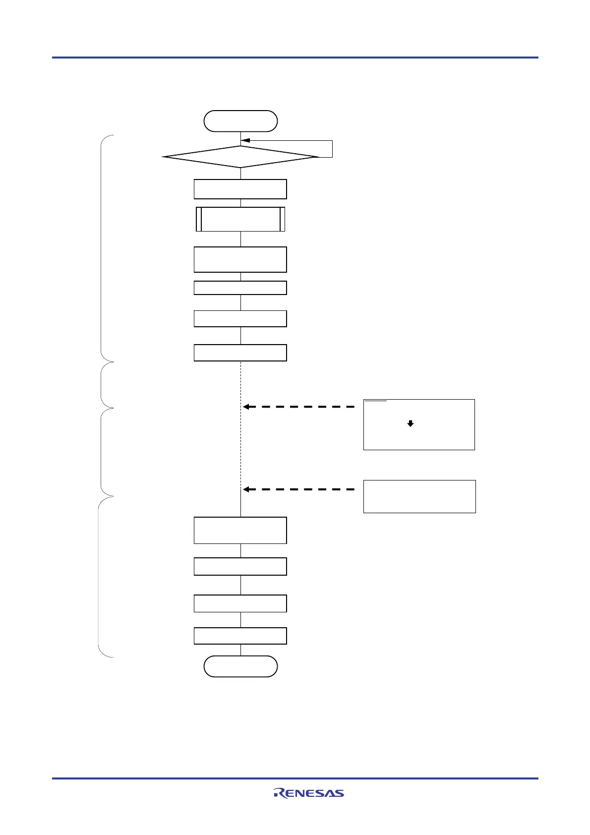
Figure 12-73. Flowchart of SNOOZE Mode Operation (once startup)
SCKp edge detected
(Entered the SNOOZE mode)
Supplying a clock to CSIp
(CSIp is receive operation)
TSFmn = 0 for all channels?
No
Yes
Write STm0 bit to 1
SAU default setting
Setting SSCm register
(SWCm = 1, SSECm = 0)
Entered the STOP mode
Reading receive data to
SIOp (=SDRmn[7:0])
Write STm0 bit to 1
Write SWCm bit to 1
Write SSm0 bit to 1
Setting SNOOZE mode
CLK supplied to the SAU is stopped.
<1>
<2>
<3>
<4>
<5>
<7>
<8>
<9>
<10>
Reset SNOOZE mode setting
<6>
The mode switches from SNOOZE to normal operation.
Become the communication wait status (SEm0 = 1)
Starting setting
Transfer interrupt (INTCSIp) is
generated
(CSIp is receive completion)
End of SNOOZE mode
Write SSm0 bit to 1
<11>
Become the operation STOP status (SEm0 = 0)
SMRm0, SCRm0 : Communication setting
SDRm0[15:9] : Setting 0000000B
Become the operation STOP status (SEm0 = 0)
It becomes communication ready state (SEm0 = 1) under
normal operation
Clear interrupt request flag (XXIF), reset interrupt mask (XXMK)
and set interrupt enable (EI).
Enables interrupt
Normal operation
SNOOZE mode
STOP mode Normal operation
Remarks 1. <1> to <11> in the figure correspond to <1> to <11> in Figure 12-72. Timing Chart of SNOOZE
Mode Operation (once startup).
2. 24 to 64-pin products: m = 0; p = 00
80, 100, 128-pin products: m = 0, 1; p = 00, 20
<R>
<R>

 Loading...


