RL78/G13 CHAPTER 12 SERIAL ARRAY UNIT
R01UH0146EJ0100 Rev.1.00 633
Sep 22, 2011
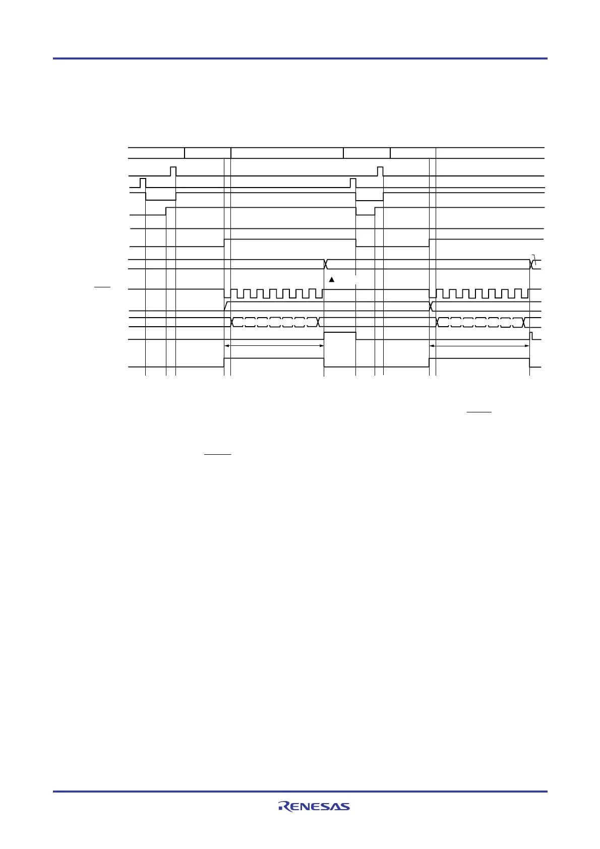
(2) SNOOZE mode operation (continuous startup)
Figure 12-74. Timing Chart of SNOOZE Mode Operation (continuous startup) (Type 1: DAPmn = 0, CKPmn = 0)
SSm0
SEm0
SWCm
SSECm L
SDRm0
INTCSIp
TSFm0
STm0
CPU operation status
Normal peration
Normal peration
STOP mode
Clock request signal
(internal signal)
SCKp pin
SNOOZE mode
STOP mode
SNOOZE mode
SIp pin
<1> <2> <3> <5> <7>
<6>
<2> <3> <5>
<6>
<9>,
<10>
<4> <4>
Note 2
Shift register
m0
Data reception (8-bit length) Data reception (8-bit length)
Receive data 2
Receive data 2
Receive data 1
Receive data 1
<8>
Read
Note1
Reception & shift operationReception & shift operation
Notes 1. Only read received data while SWCm = 1 and before the next edge of the SCKp pin input is
detected.
2. The transfer end interrupt (INTCSIp) is cleared either when SWCm is cleared to 0 or when the
next edge of the SCKp pin input is detected.
Caution Before switching to the SNOOZE mode or after reception operation in the SNOOZE mode
finishes, be sure to set the STm0 bit to 1 and clear the SEm0 bit (to stop the operation).
Remarks 1. <1> to <10> in the figure correspond to <1> to <10> in Figure 12-75. Flowchart of SNOOZE Mode
Operation (continuous startup).
2. 24 to 64-pin products: m = 0; p = 00
80, 100, 128-pin products: m = 0, 1; p = 00, 20
<R>

 Loading...


