Rockwell Automation Publication 2198-UM001D-EN-P - May 2014 221
Sizing Multi-axis Shared-bus Configurations Appendix C
Table 89 - Control Power Current Demand
Kinetix 5500 System Current Demand Example
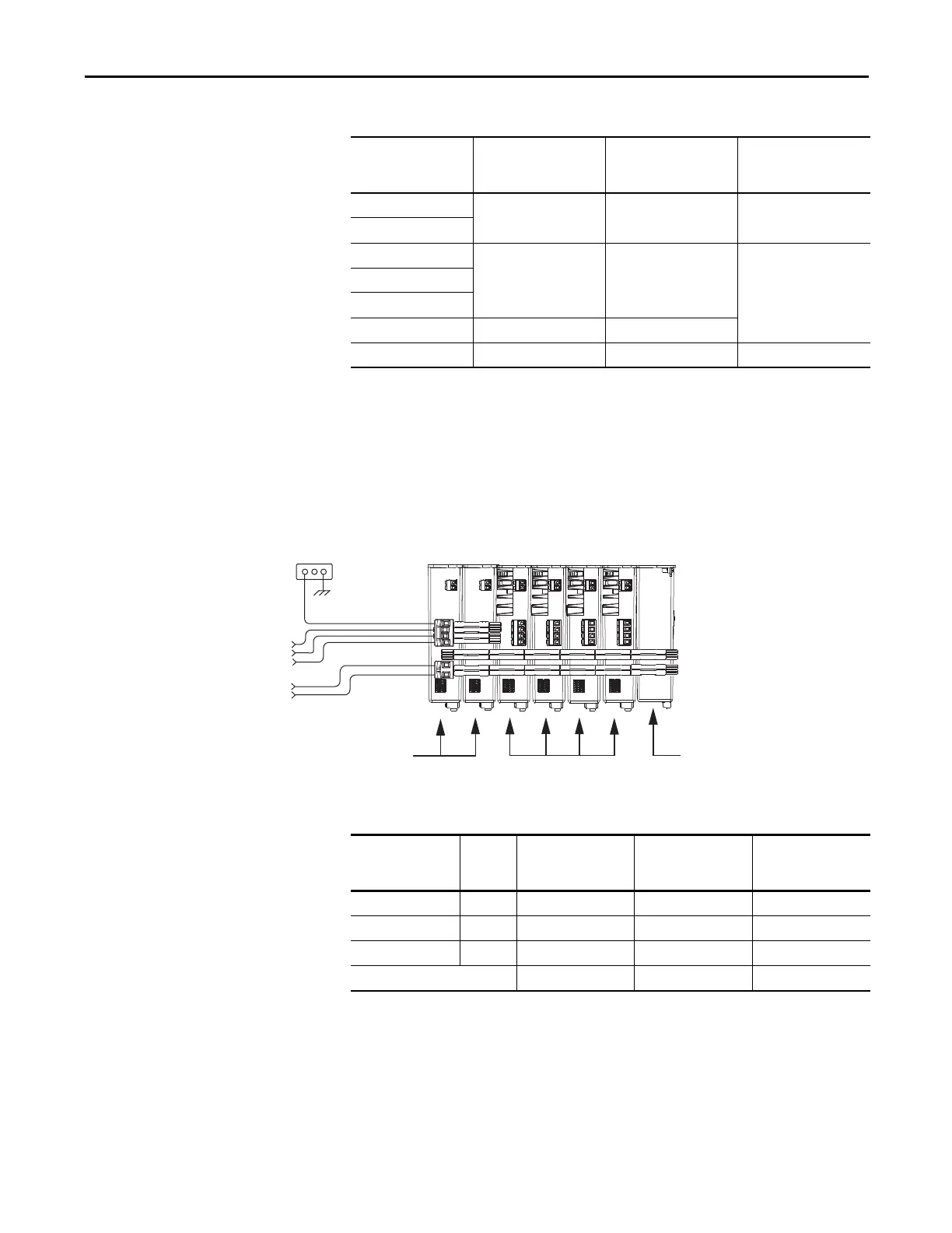
In this example, the Kinetix 5500 drive system includes two 2198-H040-ERS
drives, four 2198-H008-ERS drives, and one capacitor module.
Figure 106 - Shared AC/DC Hybrid Configuration
Table 90 - Kinetix 5500 System Current Demand Calculations
Cat. No.
24V Current
(non-brake motor)
A
DC
24V Current
(2 A brake motor)
A
DC
24V Inrush Current
(1)
A
(1) Inrush current duration is less than 30 ms.
2198-H003-ERSx
0.4 2.4 2.0
2198-H008-ERSx
2198-H015-ERSx
0.8 2.8
3.0
2198-H025-ERSx
2198-H040-ERSx
2198-H070-ERSx 1.3 3.3
2198-CAPMOD-1300 0.3 N/A 2.0
Bonded Cabinet
Ground
Three-phase
Input Power
24V Input
Control Power
3.5 A min, non-brake motors
15.2 A min, brake motors
2198-H040-ERS
Servo Drives
2198-H008-ERS
Servo Drives
2198-CAPMOD-1300 Capacitor Module
DC Bus Connections
Kinetix 5500 Module
Cat. No.
Qty
24V Current
(non-brake motors)
A
DC
24V Current
(2 A brake motors)
A
DC
24V Inrush Current
(1)
A
(1) Inrush current duration is less than 30 ms.
2198-H008-ERSx 4 0.4 x 4 = 1.6 2.4 x 4 = 9.6 2 x 4 = 8
2198-H040-ERSx 2 0.8 x 2 = 1.6 2.8 x 2 = 5.6 3 x 2 = 6
2198-CAPMOD-1300 1 0.3 x 1 = 0.3 N/A 2 x 1 = 2
Total current demand 3.5 15.2 16

 Loading...


