Rockwell Automation Publication 2198-UM001D-EN-P - May 2014 49
Mounting the Kinetix 5500 Drive System Chapter 3
Drilling Hole Patterns
Hole patterns for drives mounted in zero-stack or shared-bus configuration are
provided for mounting your drives to the panel. Drives with the highest power
rating are always mounted to the left of any drive with a lower power rating in
shared-bus configurations:
• Frame 1 drives can be followed by only another frame 1 drive.
• Frame 2 drives can be followed by frame 1 drives or another frame 2 drive.
• Frame 3 drives can be followed by frame 1, frame 2, or another frame 3
drive.
• Mount Bulletin 2198 capacitor modules in the rightmost position.
– Capacitor modules have the same hole pattern as frame 2 drives.
– Only Shared DC, Shared AC/DC, and Shared AC/DC, hybrid
configurations are compatible with Bulletin 2198 capacitor modules.
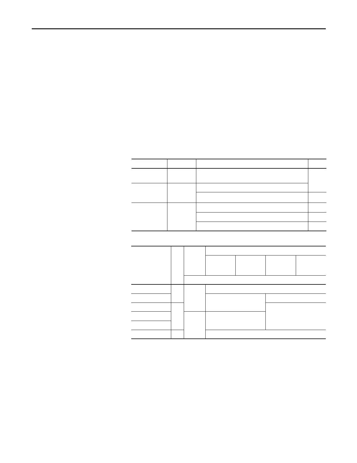
Table 17 - Hole Pattern Overview
Table 18 - Capacitor Module Support
Drive Cat. No. Frame Size Frame Size Patterns Page
2198-H003-ERSx
2198-H008-ERSx
Frame 1 As many as eight frame 1 drives
51
2198-H015-ERSx
2198-H025-ERSx
2198-H040-ERSx
Frame 2
As many as 8 frame 2 drives
One frame 2 drive followed by as many as seven frame 1 drives 52
2198-H070-ERSx Frame 3
As many as 8 frame 3 drives 53
One frame 3 drive followed by as many as seven frame 1 drives 54
One frame 3 drive followed by as many as seven frame 2 drives 55
Drive Cat. No.
Frame Size
Standalone
Single Phase
Operation
Three-phase Operation
Standalone Shared DC Shared AC/DC
Shared AC/DC
Hybrid
Number of capacitor modules connected, max
2198-H003-ERSx
(1)
(1) Catalog number 2198-H003-ERS and any drive in standalone single-phase operation is not compatible with the Kinetix 5500
capacitor module.
1
0
0
2198-H008-ERSx
(1)
1
2
2198-H015-ERSx
(1)
242198-H025-ERSx
N/A
3
2198-H040-ERSx
2198-H070-ERSx 34

 Loading...


