Rockwell Automation Publication 2198-UM001D-EN-P - May 2014 59
Connector Data and Feature Descriptions Chapter 4
Safe Torque-off Connector Pinout
For the hardwired safe torque-off (STO) connector pinouts, feature descriptions,
and wiring information, refer to Chapter
9 beginning on page 157.
Input Power Connector Pinouts
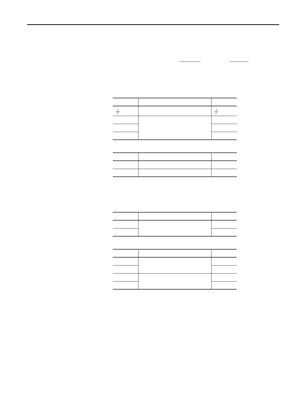
Table 19 - Mains Input Power Connector
Table 20 - 24V Input Power Connector
DC Bus and Shunt Resistor Connector Pinouts
Table 21 - DC Bus Power Connector
Table 22 - Shunt Resistor Connector
IPD Pin Description Signal
Chassis ground
L3
Three-phase input power
L3
L2 L2
L1 L1
CP Pin Description Signal
1 24V power supply, customer supplied 24V+
2 24V common 24V-
DC Pin Description Signal
1
DC bus connections
DC-
2DC+
RC Pin Description Signal
1
Shunt connections (frames 2 and 3)
DC+
2SH
1
Shunt connections (frame 1)
SH
2DC+

 Loading...


