Rockwell Automation Publication 2198-UM001D-EN-P - May 2014 75
Connecting the Kinetix 5500 Drive System Chapter 5
Wiring Requirements
Wires must be copper with 75 °C (167 °F) minimum rating. Phasing of main AC
power is arbitrary and earth ground connection is required for safe and proper
operation.
Refer to Power Wiring Examples
on page 190 for interconnect diagrams.
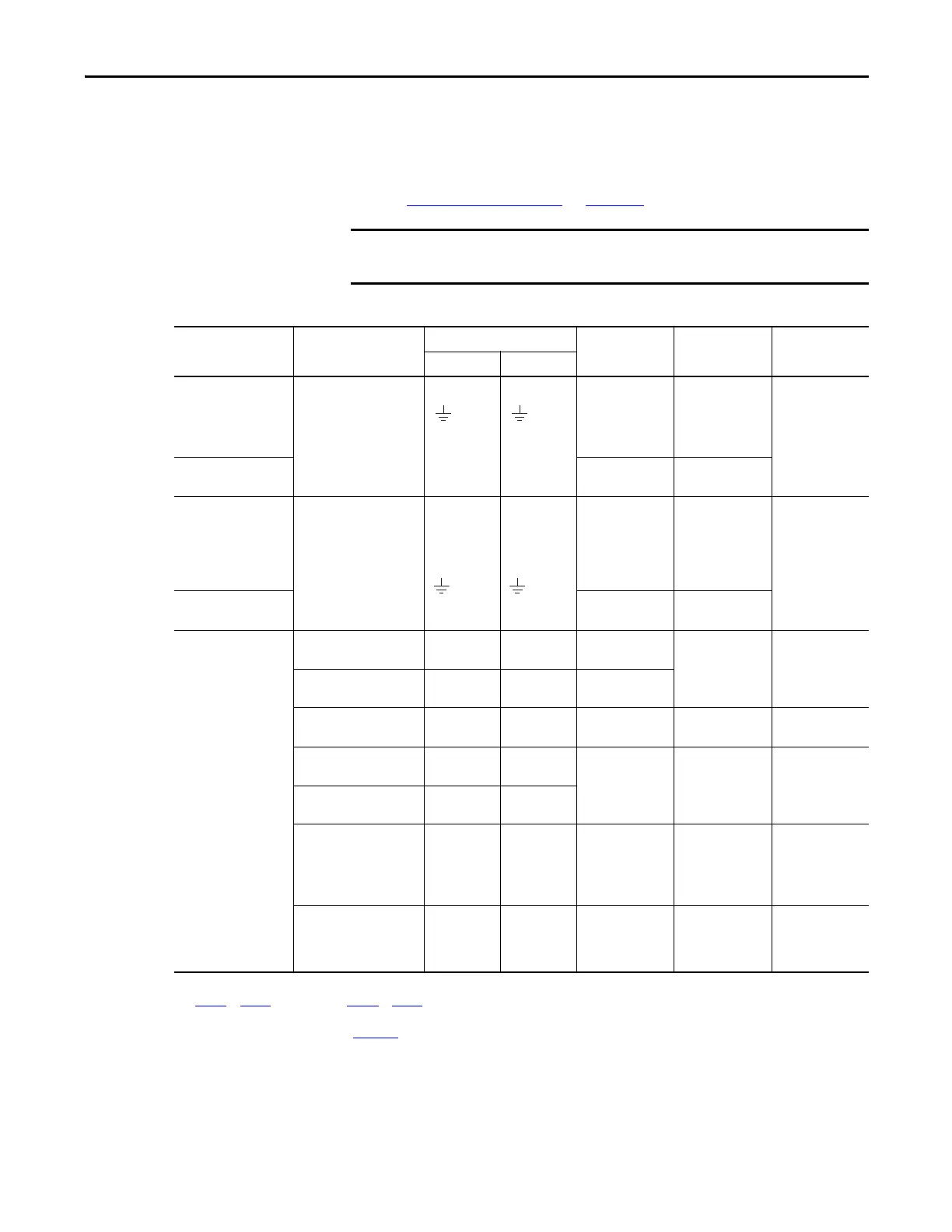
Table 31 - Power and I/O Wiring Requirements
The National Electrical Code and local electrical codes take precedence over
the values and methods provided.
Kinetix 5500 Drive
Cat. No.
Description
Connects to Terminals
Wire Size
mm
2
(AWG)
Strip Length
mm (in.)
Torque Value
N•m (lb•in)
Pin Signal
2198-H003-ERSx
2198-H008-ERSx
2198-H015-ERSx
2198-H025-ERSx
2198-H040-ERSx
Mains input power
(1)
(single-axis IPD connector)
1.5…4
(16…12)
8.0 (0.31)
0.5…0.6
(4.4…5.3)
2198-H070-ERSx
1.5…6
(16…10)
10.0 (0.39)
2198-H003-ERSx
2198-H008-ERSx
2198-H015-ERSx
2198-H025-ERSx
2198-H040-ERSx
Motor power
Motor power cable
depends on motor/
drive combination.
0.75…2.5
(2)
(18…14)
8.0 (0.31)
0.5…0.6
(4.4…5.3)
2198-H070-ERSx
2.5…6
(2)
(14…10)
10.0 (0.39)
2198-xxxx-ERSx
PELV/SELV 24V power
(1)
(single-axis CP connector)
CP-1
CP-2
24V+
24V-
2.5…0.5
(14…20)
7.0 (0.28)
0.22…0.25
(1.9…2.2)
Brake power
BC-1
BC-2
MBRK+
MBRK-
N/A
(3)
DC Bus power
DC-1
DC-2
DC-
DC+
N/A
(4)
N/A
(4)
N/A
(4)
Shunt resistor
(frame 2 and 3)
RC-1
RC-2
DC+
SH
4…0.5
(12…20)
8.0 (0.31)
0.5…0.6
(4.4…5.3)
Shunt resistor
(frame 1)
RC-1
RC-2
SH
DC+
Safety
(5)
ST0-1
ST0-2
ST0-3
ST0-4
ST0-5
SB+
SB-
S1
SC
S2
1.5…0.2
(16…24)
10.0 (0.39) N/A
(6)
Digital inputs
IOD-1
IOD-2
IOD-3
IOD-4
IN1
(7)
COM
IN2
SHLD
1.5…0.2
(16…24)
10.0 (0.39) N/A
(6)
(1) The wire size, strip length, and torque specifications shown here apply to the single-axis connector that ships with the drive. For the shared-bus connector specifications, refer to
Tab le 33
on page 77 (CP connector) and Table 3 5 on page 79 (IPD connector).
(2) Building your own cables or using third-party cables is not an option. Use single motor cable catalog number 2090-CSxM1DF-xxAAxx. Refer to the Kinetix Motion Accessories
Specifications Technical Data, publication GMC-TD004
, for cable specifications.
(3) Motor brake wires are part of the 2090-CSBM1DF-xxAAxx motor cable.
(4) DC bus connections are always made from drive-to-drive over the bus bar connection system. These terminals do not receive discrete wires.
(5) These signals and the safe torque-off (STO) connector apply to only the 2198-Hxxx-ERS drives.
(6) This connector uses spring tension to hold wires in place.
(7) This signal has dual-functionality. You can use IN1 (IOD-1) as registration or Home input.

 Loading...


