58 Rockwell Automation Publication 2198-UM001D-EN-P - May 2014
Chapter 4 Connector Data and Feature Descriptions
Kinetix 5500 Connector Data
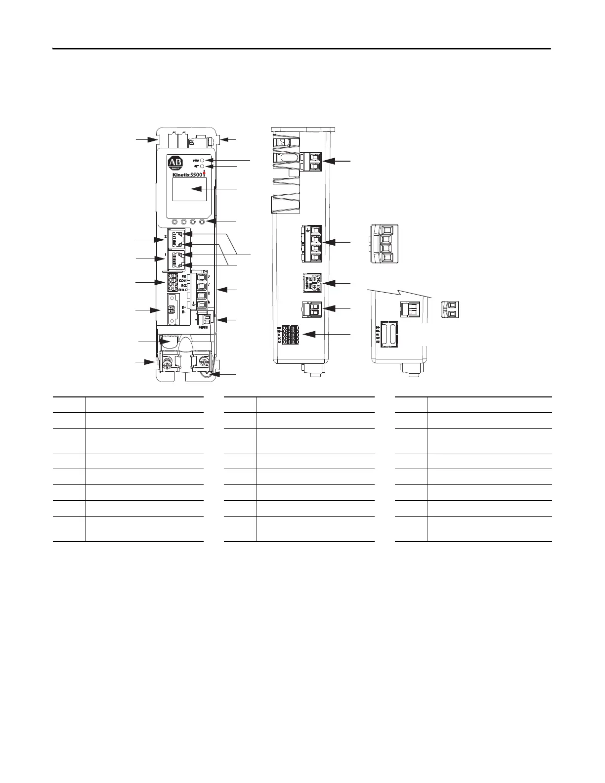
Use these illustrations to identify the connectors and indicators for the
Kinetix 5500 servo drives.
Figure 28 - Kinetix 5500 Drive Features and Indicators
Item Description Item Description Item Description
1 Motor cable shield clamp 8 Module status indicator 15 Motor brake (BC) connector
2
Converter kit mounting hole
(1)
(under cover)
9 Network status indicator 16 Ground terminal
3 Motor feedback (MF) connector 10 LCD display 17 Shunt resistor (RC) connector
4 Digital inputs (IOD) connector 11 Navigation pushbuttons 18 AC mains input power (IPD) connector
5 Ethernet (PORT1) RJ45 connector 12 Link speed status indicators 19 DC bus (DC) connector (under cover)
(2)
6 Ethernet (PORT2) RJ45 connector 13 Link/Activity status indicators 20 24V control input power (CP) connector
7 Zero-stack mounting tab/cutout 14 Motor power (MP) connector 21
Safe torque-off (STO) connector
(3)
(does not apply to 2198-Hxxx-ERS2 drives)
(1) Protective knock-out covers the 2198-H2DCK Hiperface-to-DSL feedback converter kit mounting hole. Remove knock-out for use with the converter kit.
(2) DC bus connector ships with protective knock-out cover that can be removed for use in shared-bus configurations.
(3) Protective knock-out cover is removed on 2198-Hxxx-ERS (hardwired STO) drives.
21
20
19
18
17
1
2
L3
L2
L1
1
2
+
–
1
8
3
4
13
5
6
11
10
9
12
16
7
7
U
V
W
2
1
15
14
2
1
2
Kinetix 5500 Drive, Front View
(2198-H003-ERSx drive is shown)
Kinetix 5500, Top View
(2198-H003-ERS drive is shown)
Kinetix 5500, Top View
(2198-Hxxx-ERS2 drives)
Protective
Knock-out
Shared-bus AC Input
Wiring Connector
Shared-bus 24V Input
Wiring Connector

 Loading...


