80 Rockwell Automation Publication 2198-UM001D-EN-P - May 2014
Chapter 5 Connecting the Kinetix 5500 Drive System
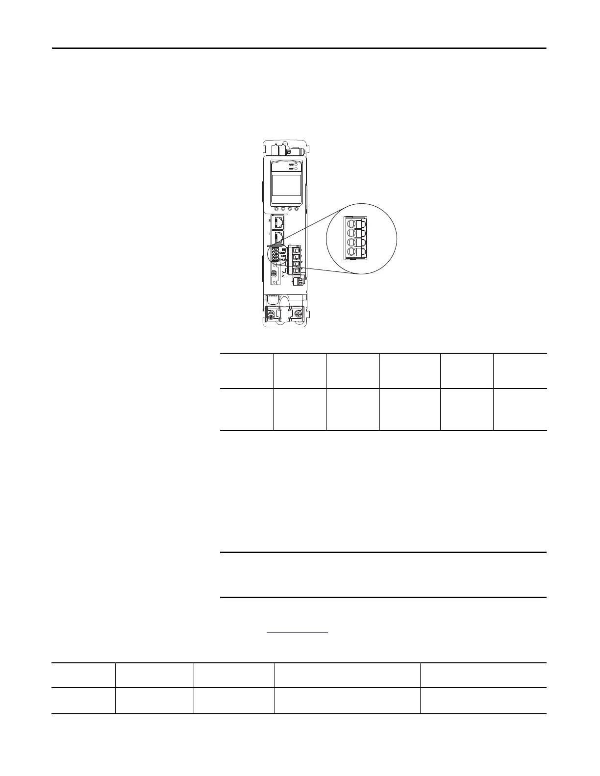
Wire the Digital Inputs Connector
The digital inputs (IOD) connector uses spring tension to hold wires in place.
Figure 45 - IOD Connector Wiring
Table 36 - Digital Inputs (IOD) Connector Specifications
Wiring Kinetix VP Motors
The Kinetix 5500 drives with Kinetix VP motors use a single cable that includes
conductors for motor power, brake, and encoder feedback. Standard and
continuous-flex (Bulletin 2090) cables are available with and without the motor
brake conductors.
Refer to the Kinetix Motion Accessories Specifications Technical Data,
publication GMC-TD004
, for cable specifications.
Table 37 - Single Cable Catalog Numbers
Digital Inputs (IOD) Connector Plug
Kinetix 5500 Servo Drive
(front view)
Drive Cat. No. DC Pin Signal
Recommended
Wire Size
mm
2
(AWG)
Strip Length
mm (in.)
Torque Value
N•m (lb•in)
2198-Hxxx-ERSx
IOD-1
IOD-2
IOD-3
IOD-4
IN1
(1)
COM
IN2
SHLD
(1) This signal has dual-functionality. You can use IN1 (IOD-1) as registration or Home input.
1.5…0.2
(16…24)
10.0 (0.39) N/A
(2)
(2) This connector uses spring tension to hold wires in place.
Due to the unique characteristics of single cable technology, designed for
and tested with Kinetix 5500 drives and Kinetix VP motors, you cannot
build your own cables or use third-party cables.
Motor Family Feedback Kit Cat. No. Motor Cat. No.
Motor Cable Cat. No.
(with brake wires)
Motor Cable Cat. No.
(without brake wires)
Kinetix VP 2198-KITCON-DSL
VPL-A/Bxxxx, VPF-A/Bxxxx,
and VPS-Bxxxxx
2090-CSBM1DF-xxAAxx (standard) cables
2090-CSBM1DF-xxAFxx (continuous-flex) cables
2090-CSWM1DF-xxAAxx (standard) cables

 Loading...


