70 Rockwell Automation Publication 2198-UM001D-EN-P - May 2014
Chapter 5 Connecting the Kinetix 5500 Drive System
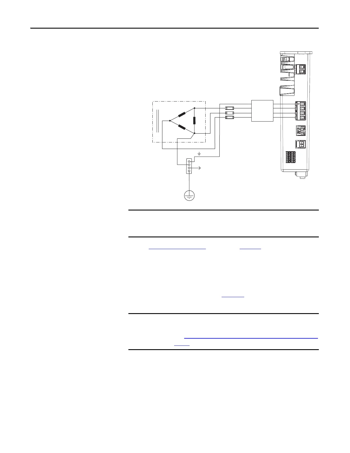
Figure 36 - Corner Grounded (B-phase) Power Configuration (Delta Secondary)
Refer to Power Wiring Examples beginning on page 190 for input power
interconnect diagrams.
Ungrounded Power Configurations
The ungrounded power configuration (Figure 37) does not provide a neutral
ground point.
Transformer (Delta) Secondary
Bonded Cabinet
Ground
Transformer
Ground Grid or
Power Distribution Ground
Connect to ground stud.
Three-phase
AC Line Filter
Input Fusing
Kinetix 5500 Servo Drive
(top view)
Even though corner-grounded power configurations have a ground
connection, treat them as ungrounded when installing Kinetix 5500 drive
systems.
If you determine that you have ungrounded or high-impedance grounded
power distribution in your facility, you need to remove the grounding screws.
Refer to Removing the Grounding Screws in Ungrounded Power Configurations
on page 71
for more information.

 Loading...


