Rockwell Automation Publication 2198-UM001D-EN-P - May 2014 61
Connector Data and Feature Descriptions Chapter 4
Motor Power, Brake, and Feedback Connector Pinouts
Table 23 - Motor Power Connector
Table 24 - Motor Brake Connector
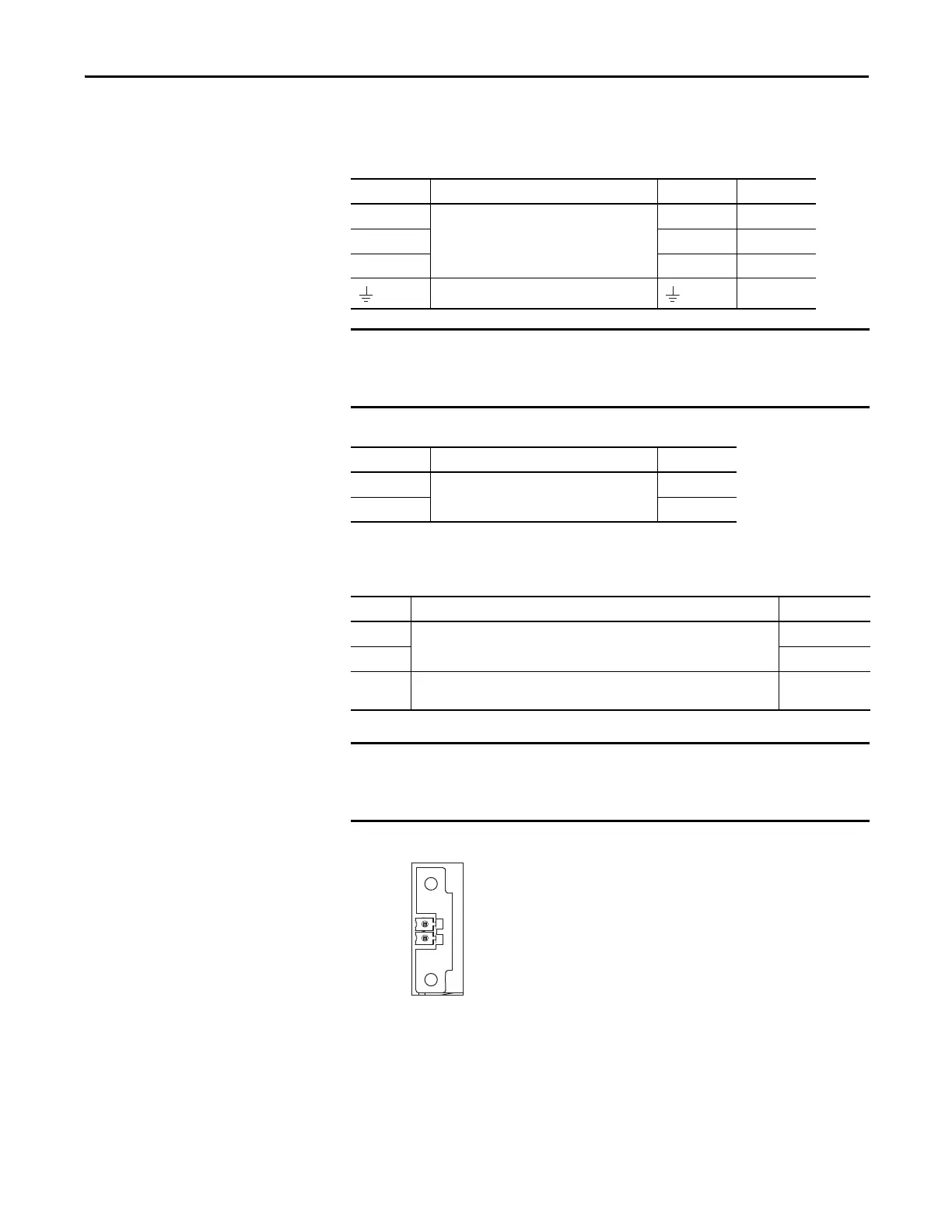
Motor Feedback Connector Pinout
Figure 31 - Pin Orientation for 2-pin Motor Feedback (MF) Connector
MP Pin Description Signal Color
U
Three-phase motor power
UBrown
VVBlack
WWBlue
Chassis ground Green
Drive-to-motor power cables must not exceed 50 m (164 ft).
System performance was tested at this cable length. These limitations also
apply when meeting CE requirements.
BC Pin Description Signal
1
Motor brake connections
MBRK+
2MBRK-
MF Pin Description Signal
1
Bidirectional data and power for digital encoder interface
D+
2D-
SHIELD
Cable shield and grounding plate (internal to 2198-KITCON-DSL connector kit)
termination point.
SHIELD
Drive-to-motor power cables must not exceed 50 m (164 ft).
System performance was tested at these cable length specifications. These
limitations also apply when meeting CE requirements.
Pin 1
Pin 2

 Loading...


