Rockwell Automation Publication 2198-UM001D-EN-P - May 2014 77
Connecting the Kinetix 5500 Drive System Chapter 5
Wiring the Power Connectors
This section provides examples and guidelines to assist you in making
connections to the input power connectors.
Refer to Power Wiring Examples
on page 190 for an interconnect diagram.
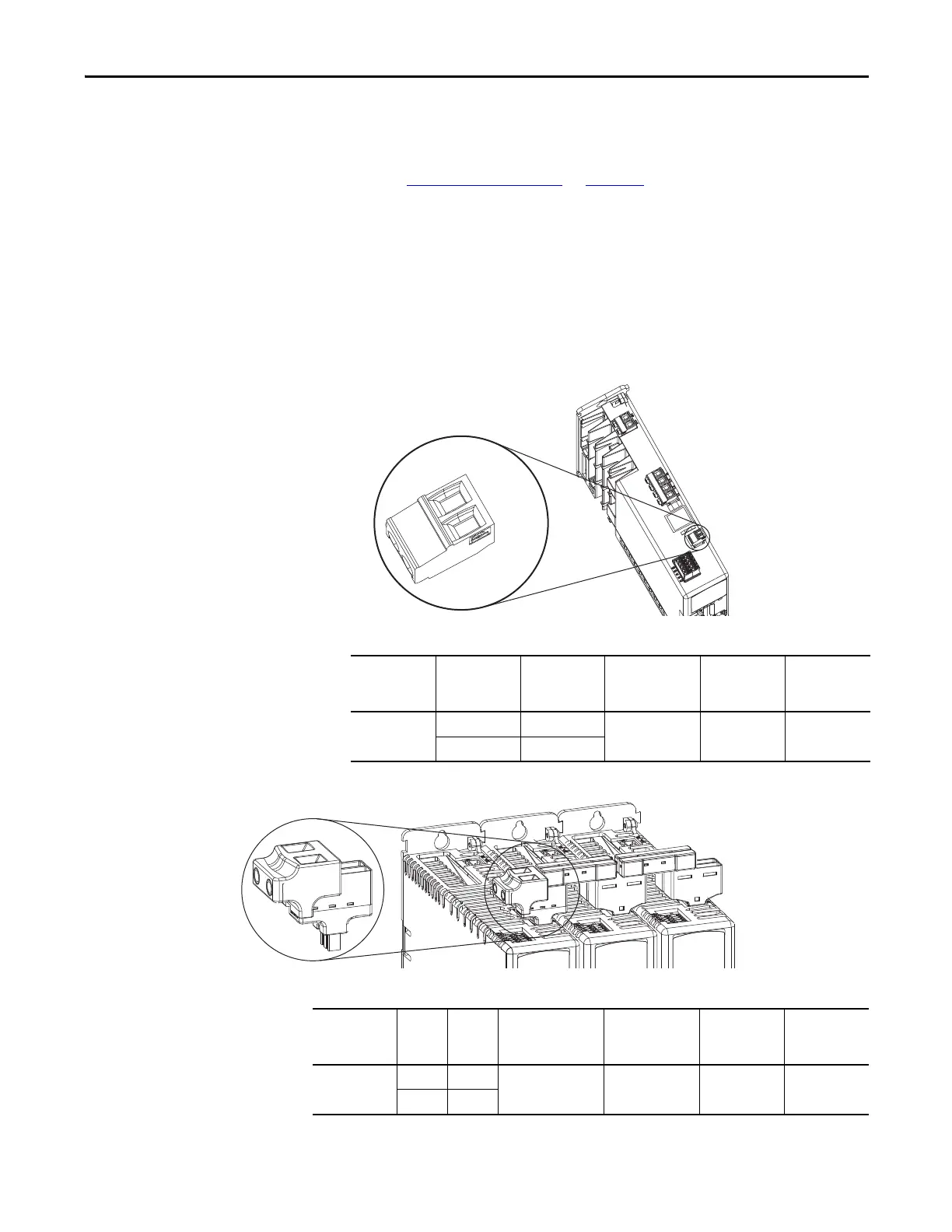
Wire the 24V Control Power Input Connector
The 24V power (CP) connector requires 24V DC input for the control circuitry.
The single-axis connector ships with the drive, shared-bus connector kits are
purchased separately.
Figure 41 - CP Connector Wiring - Single Axis
Table 32 - Single Axis CP Connector Wiring Specifications
Figure 42 - CP Connector Wiring - Shared Bus
Table 33 - Shared Bus CP Connector Wiring Specifications
24V-
24V+
1
2
Remove
For DC
Bus Only
Kinetix 5500 Drive
Top View
24V (CP) Connector Plug
Drive Cat. No. CP Pin Signal
Recommended
Wire Size
mm
2
(AWG)
Strip Length
mm (in.)
Torque Value
N•m (lb•in)
2198-Hxxx-ERSx
CP-1 24V+
2.5…0.5
(14…20)
7.0 (0.28)
0.22…0.25
(1.9…2.2)
CP-2 24V-
Kinetix 5500 Drives
Top View
24V DC Input
Wiring Connector
Drive Cat. No. CP Pin Signal
Input Current, max
A rms
Recommended
Wire Size
mm
2
(AWG)
Strip Length
mm (in.)
Torque Value
N•m (lb•in)
2198-Hxxx-ERSx
CP-1 24V+
32 8.4 (8) 11.0 (0.43)
1.7…1.8
(15.0…15.9)
CP-2 24V-

 Loading...


