38 Rockwell Automation Publication 2198-UM001D-EN-P - May 2014
Chapter 2 Planning the Kinetix 5500 Drive System Installation
Bonding Multiple Subpanels
Bonding multiple subpanels creates a common low impedance exit path for the
high frequency energy inside the cabinet. Subpanels that are not bonded together
do not necessarily share a common low impedance path. This difference in
impedance can affect networks and other devices that span multiple panels:
• Bond the top and bottom of each subpanel to the cabinet by using
25.4 mm (1.0 in.) by 6.35 mm (0.25 in.) wire braid. As a rule, the wider
and shorter the braid is, the better the bond.
• Scrape the paint from around each fastener to maximize metal-to-metal
contact.
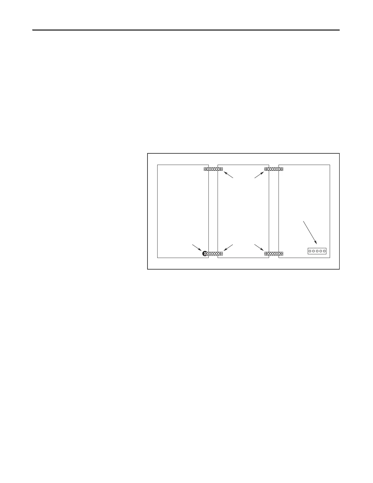
Figure 15 - Multiple Subpanels and Cabinet Recommendations
Wire Braid
25.4 mm (1.0 in.) by
6.35 mm (0.25 in.)
Paint removed
from cabinet.
Cabinet ground bus
bonded to the subpanel.
Wire Braid
25.4 mm (1.0 in.) by
6.35 mm (0.25 in.)

 Loading...


