62 Rockwell Automation Publication 2198-UM001D-EN-P - May 2014
Chapter 4 Connector Data and Feature Descriptions
Understanding Control
Signal Specifications
This section provides a description of the Kinetix 5500 digital inputs, Ethernet
communication, power and relay specifications, encoder feedback specifications,
and safe torque-off features.
Digital Inputs
Two digital inputs are available for the machine interface on the IOD connector.
Digital inputs require a 24V DC @ 15 mA supply. These are sinking inputs that
require a sourcing device. A common and cable shield connection is provided on
the IOD connector for digital inputs.
The Registration 1 input is capable of dual functionality. You can also use this as
the Home input. Configuration for dual functionality is not needed.
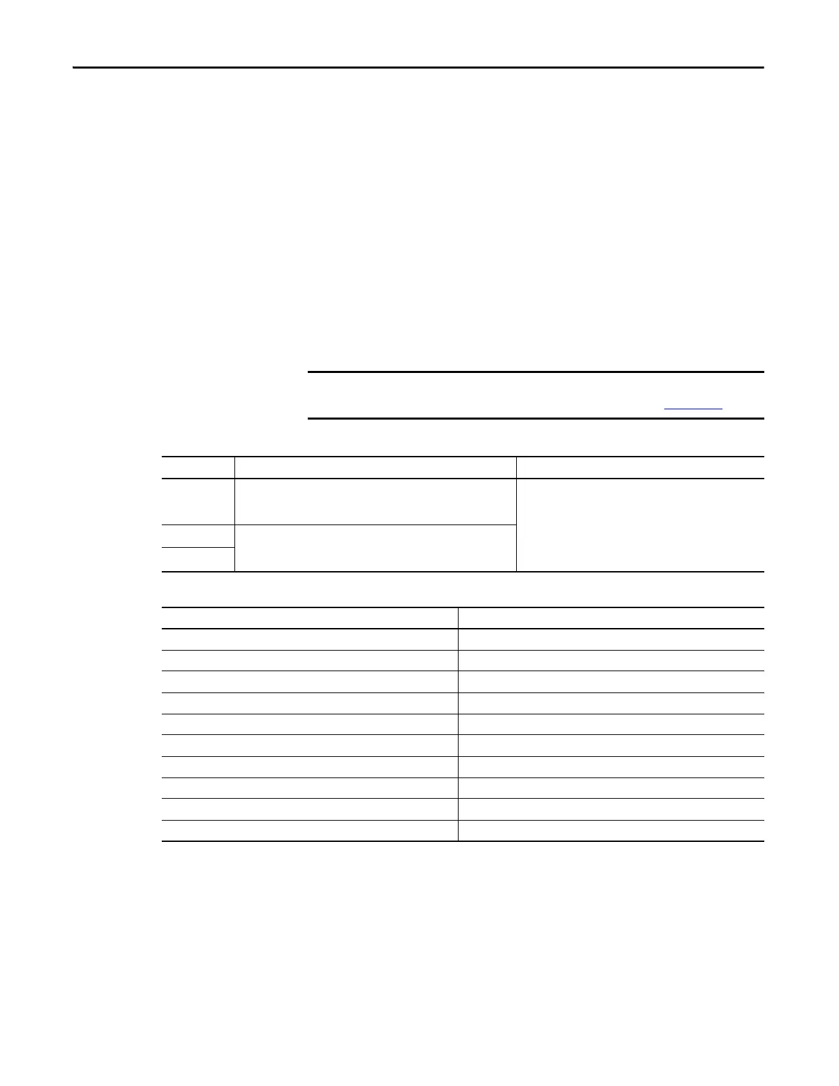
Table 25 - Understanding Digital Input Functions
Table 26 - Digital Input Specifications
To improve registration input EMC performance, refer to the System Design for
Control of Electrical Noise Reference Manual, publication GMC-RM001
.
Function Description Default Behavior
Home/Reg1
An active state indicates to a homing sequence that the referencing
sensor has been seen. Typically, a transition of this signal is used to
establish a reference position for the machine axis.
The function is always inactive. You can enable in the Logix
Designer application.
Registration 1 An inactive-to-active transition (also known as a positive transition) or
active-to-inactive transition (also known as a negative transition) is
used to latch position values for use in registration moves.
Registration 2
Attribute Value
Type Active high, single-ended, current sinking (EN 61131-2 Type 1)
Dedicated functions Registration 1, Home, Registration 2
Input current (with 24V applied) 12 mA, typical
On-state input voltage 15…30V @ 15 mA, max
Off-state input voltage -1.0…5.0V
Pulse reject filtering (registration functions) 12.0 μs
Pulse reject filtering (home input function) debounce filter 20 ms, nom
Propagation delay (registration functions) 0 (delay compensated)
Registration repeatability 700 ns
Windowed registration invalid-to-valid event delay 125 μs, min

 Loading...


