Rockwell Automation Publication 2198-UM001D-EN-P - May 2014 79
Connecting the Kinetix 5500 Drive System Chapter 5
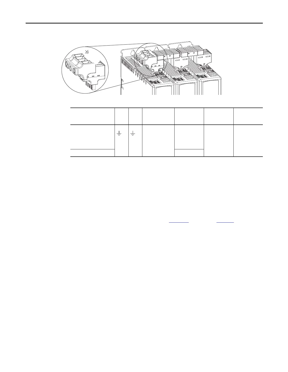
Figure 44 - IPD Connector Wiring - Shared Bus
Table 35 - Shared Bus IPD Connector Wiring Specifications
Wiring the Digital Input
Connectors
This section provides guidelines to assist you in making digital input
connections.
Wire the Safe Torque-off Connector
For the hardwired safe torque-off (STO) connector pinouts, feature descriptions,
and wiring information, refer to Chapter
9 beginning on page 157.
Kinetix 5500 Drives
Top View
Mains AC Input
Wiring Connector
Kinetix 5500 Drive
Cat. No.
Pin Signal
Input Current, max
A rms
Recommended
Wire Size
mm
2
(AWG)
Strip Length
mm (in.)
Torque Value
N•m (lb•in)
2198-H003-ERSx
2198-H008-ERSx
2198-H015-ERSx
2198-H025-ERSx
2198-H040-ERSx
52
13.3…3.3
(6…12)
11.0 (0.43)
1.7…1.8
(15.0…15.9)
2198-H070-ERSx 13.3 (6)

 Loading...


