64 Rockwell Automation Publication 2198-UM001D-EN-P - May 2014
Chapter 4 Connector Data and Feature Descriptions
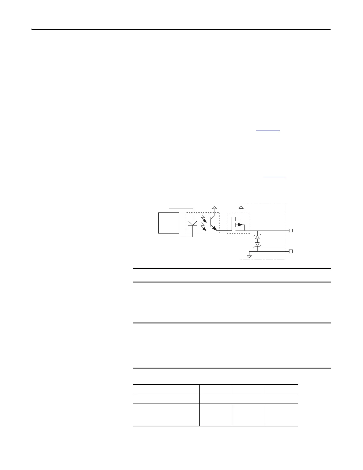
Motor Brake Circuit
The customer-supplied 24V power supply drives the motor parking-brake output
through a solid-state relay. The solid-state brake driver circuit provides the
following:
• Brake thermal-overload protection
• Brake current-overload protection
• Brake over-voltage protection
Two connections (BC-1 and BC-2) are required for the motor brake output.
Connections are rated for 2.0 A @ +24V (refer to Figure 33
).
Control of the solid-state relay to release the motor brake is configurable in the
Logix Designer application. An active signal releases the motor brake. Turn-on
and turn-off delays are specified by the brake-active delay and brake-inactive delay
(configurable in the Logix Designer application). Refer to Kinetix 5500 Drive
and Motor/Actuator Wiring Examples beginning on page 195
for wiring
examples.
Figure 33 - Motor Brake Circuit
Control Power
The Kinetix 5500 drive requires 24V DC input power for control circuitry.
Table 27 - Control Power Input Power Specifications
ISP772
MBRK+ (BC-1)
MBRK– (BC-2)
24V PWR
24V COM
INT PWR
Kinetix 5500
Servo Drive
Control
Board
Noise
Suppression
Device
Motor parking-brake switching frequency must not exceed 10 cycles/min.
SELV and PELV rated power supplies must be used to energize external safety
devices connected to the Kinetix 5500 safety inputs.
The National Electrical Code and local electrical codes take precedence over the
values and methods provided. Implementation of these codes is the
responsibility of the machine builder.
Attribute Frame 1 Frame 2 Frame 3
Input voltage 21.6…26.4V DC
Control power AC input current
Nom @ 24V DC
(1)
Inrush, max
(1) Plus BC connector (MBRK+) current.
400 mA
2.0 A
800 mA
3.0 A
1.3 A
3.0 A

 Loading...


