Rockwell Automation Publication 2198-UM001D-EN-P - May 2014 81
Connecting the Kinetix 5500 Drive System Chapter 5
Motor Power Connections
Refer to Kinetix 5500 Drive and Motor/Actuator Wiring Examples on page 195
for an interconnect diagram.
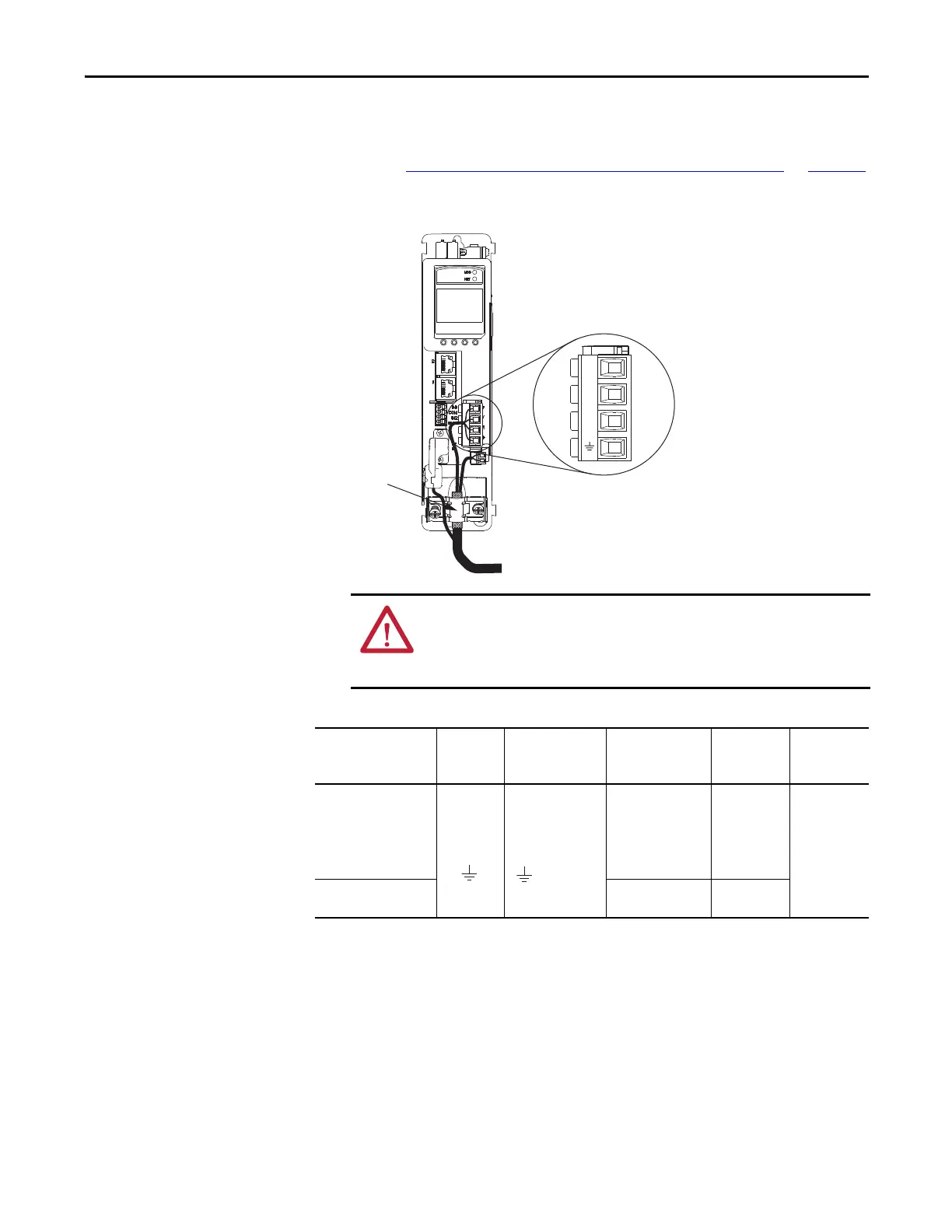
Figure 46 - MP Connector Wiring
Table 38 - Motor Power (MP) Connector Specifications
U
V
W
Motor Cable
Shield Clamp
Motor Power (MP) Connector Plug
Kinetix 5500 Servo Drive
(front view)
ATTENTION: Make sure the motor power connections are correct when wiring
the MP connector plug and that the plug is fully engaged in the module
connector. Incorrect wiring/polarity or loose wiring can cause an explosion or
damage to equipment.
Drive Cat. No. Pin Signal/Wire Color
Recommended
Wire Size
mm
2
(AWG)
Strip Length
mm (in.)
Torque Value
N•m (lb•in)
2198-H003-ERSx
2198-H008-ERSx
2198-H015-ERSx
2198-H025-ERSx
2198-H040-ERSx
Motor power cable
depends on motor/
drive combination.
0.75…2.5
(18…14) max
8.0 (0.31)
0.5…0.6
(4.4…5.3)
2198-H070-ERSx
2.5…6
(14…10) max
10.0 (0.39)
Brown
Black
Blue
Green/Yellow
U
V
W

 Loading...


