60 Rockwell Automation Publication 2198-UM001D-EN-P - May 2014
Chapter 4 Connector Data and Feature Descriptions
Digital Inputs Connector Pinout
Figure 29 - Pin Orientation for 4-pin Digital Inputs (IOD) Connector
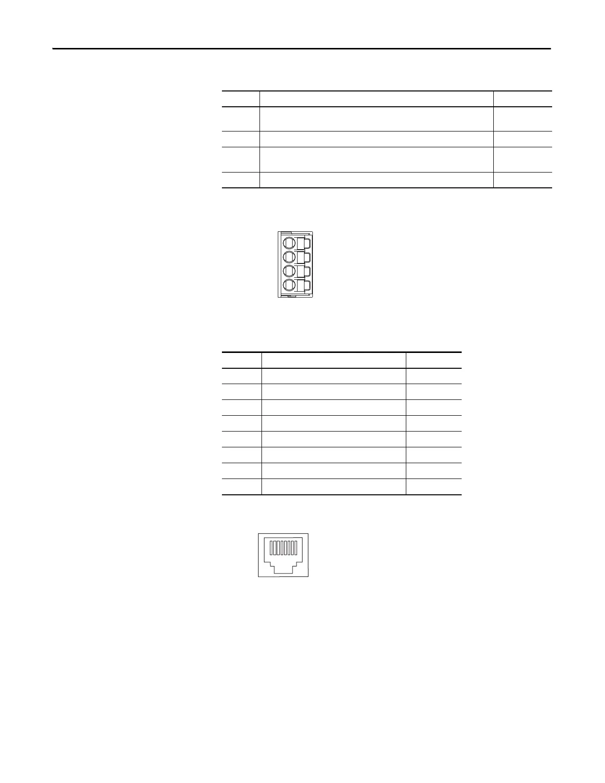
Ethernet Communication Connector Pinout
Figure 30 - Pin Orientation for 8-pin Ethernet PORT1 and PORT2 Connectors
IOD Pin Description Signal
1
High speed registration/home position input. A low/high or high/low transition
triggers a registration event. This is a dual-function input.
IN1
(1)
(1) This signal has dual-functionality. You can use IN1 (IOD-1) as registration or Home input.
2 I/O common for customer-supplied 24V supply. COM
3
High speed registration input. A low/high or high/low transition triggers a
registration event.
IN2
4 I/O cable shield termination point. SHLD
Pin 1 IN1
COM
IN2
SHLD
Pin Description Signal
1 Transmit+ TD+
2 Transmit- TD-
3 Receive+ RD+
4 Reserved –
5 Reserved –
6 Receive- RD-
7 Reserved –
8 Reserved –

 Loading...


