Parameter Description Factory setting
p1113[C] BI: Setpoint inversion Dependent on the converter
p2103[C] BI: 1. Acknowledge faults Dependent on the converter
p2106[C] BI: External fault 1 1
p2112[C] BI: External alarm 1 1
For additional binector inputs and additional information on parameters, please refer to the
parameter list.
Overview of the manuals (Page465)
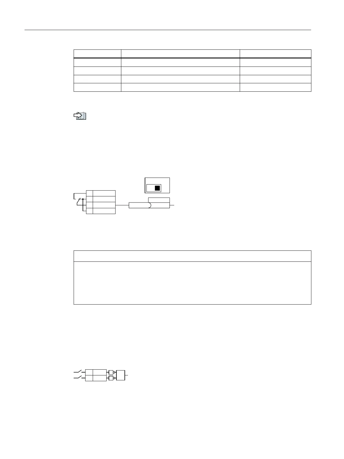
8.4.2 Analog input as digital input
Function description
9RXW
*1'
$,
$,
',
U
%,S[[[[
8,
$,
To use the analog input as additional digital input, you must connect the analog input as
shown, and interconnect status parameter r0722.11 with a binector input of your choice.
You may operate the analog input as a digital input with 10V or with 24V.
NOTICE
Defective analog input due to overcurrent
If the analog input switch is set to "Current input" (I), a 10 V or 24 V voltage source results in an
overcurrent at the analog input. An overcurrent condition destroys the analog input.
• If you use an analog input as a digital input, then you must set the analog input switch to
"Voltage" (U).
8.4.3 Failsafe digital inputs
Function description
The converter combines two digital inputs into one failsafe digital input.
Additional information on failsafe digital inputs is provided in the description of the STO
safety function.
Advanced commissioning
8.4Adapt the default setting of the terminal strip
SINAMICS G120C Converters
190 Operating Instructions, 02/2023, FW V4.7 SP14, A5E34263257B AK
 Loading...


