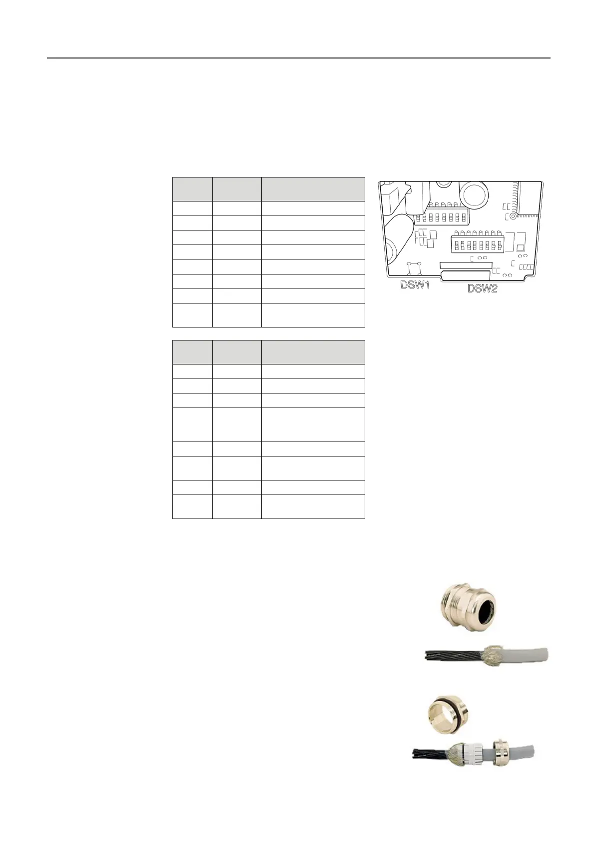
13.10. DIL Switch Settings DR-220
The switches for setting the operating mode of the DR-220 are located behind a cover on the
underside of the device (see manual).
The following factory settings are to be checked on the printer in the event of a
fault:
13.11. Assembling the EMC cable gland for data and printer cables
Step 1:
- Strip cable sheath by 100 mm
- Expose shielding braid screen and shorten to 15mm
Step 2:
- Feed cable through the union nut
- Feed cable through terminal insert
- Place shielding braid over terminal insert
- Shielding braid must extend over the O-ring
approx. 2 mm
MultiLevel Instruction Manual Other Information
Switch
DSW 1
Position Function
1 OFF Transfer error print “?“
2 ON
3 ON Handshake XON/XOFF
4 OFF 8 bits
5 ON Use Parity
6 ON Even parity
7 OFF 9600 Baud
8 ON Busy:
Switch
DSW 2
Position Function
1 ON 42/35 characters/line
2 OFF Autocutter
3 OFF - - -
4 OFF Activation of serial
interface by means of
DIP switch
5 OFF - - -
6 OFF
deactivated
7 OFF Pin6 Reset deactivated
8 OFF Pin 25 Reset
deactivated

 Loading...


