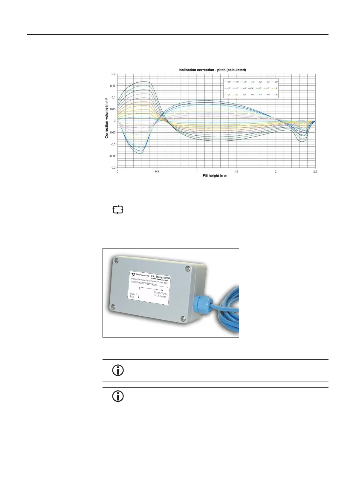
5.7.1. Graph of a typical inclination correction curve
Figure 15: Typical inclination correction curves
The graph shown above is stored as a table in the MultiLevel. Each height is
assigned an inclination correction volume. Intermediate values are interpolated
linearly.
5.7.2. Inclination Sensor
Figure 16: Inclination sensor – MLIS
The inclination sensor must be permanently installed on a stable cross beam.
The alignment of the sensor may not be changed by the external application of
force.
The inclination sensor must be installed on the tank truck with the correct
alignment. The label on the sensor is to be observed!
5.7.3. Inclination Sensor – Definition of the Angle Corrections
In order to determine the vehicle inclination with the required accuracy, the angle parameters
must be input into the system with particular care.
MultiLevel Instruction Manual Description of the Level Gauging System

 Loading...


