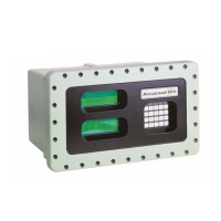
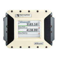
7.1.1. Display / keyboard 2 – MLMAINDISP2
The MultiLevel system is operated via the keyboard and the display.
Parts no.: MLMAINDISP2
Drawing no.: 61.352025
Wiring diagram no.: 51.351673
Figure 33: Display Interface 2 / open - with SD-card
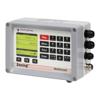
7.1.2. Display / Interface – NM2MAINDISP2
Parts no.: NM2MAINDISP2
Drawing no.: 31.352023
Wiring diagram no.: 51.351673
Figure 34: Display Interface – NM2MAINDISP2
MultiLevel Instruction Manual Modules
1
Name strip
2
Display CPU board
3
MAIN Unit CPU board
4
CPU
5
SD card PCB with
memory card
The PCB with the
internal memory card,
in which the gauge
and inclination tables
are stored, is installed
above the main unit
CPU board.
6
Setup switch: DIP 8
seal switch
1
2
3
4
5
6
Connector for
chip card reader
Connector for
chip card reader
1
Name strip
2
Display CPU board
1
2
 Loading...
