22
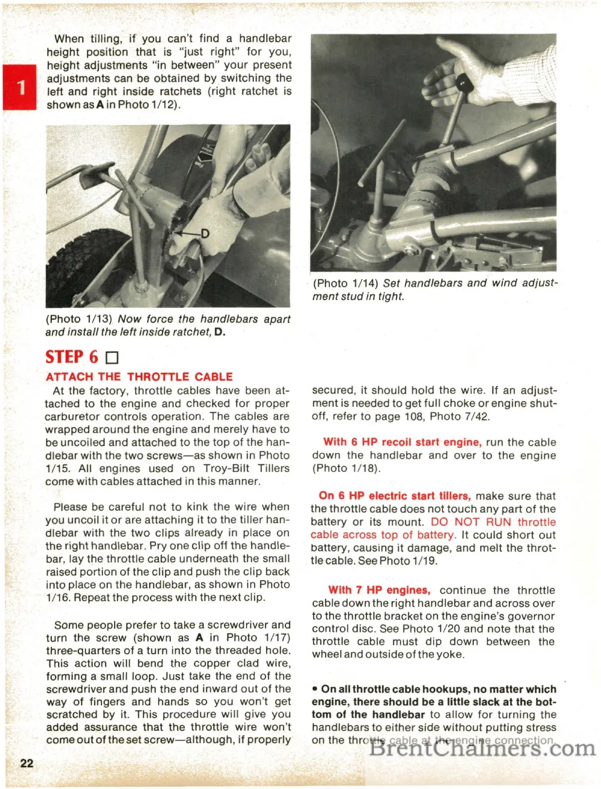
When tilling,
if
you
can't find a handlebar
height
position
that
is
"just
right"
for
you,
height
adjustments
"in
between"
your
present
adjustments can be obtained by
switching
the
left and
right
inside ratchets
(right
ratchet
is
shown
asA
in
Photo
1/12).
(Photo 1/13)
Now
force the handlebars
apart
and
install
the
left
inside ratchet, D.
STEP
6 0
ATTACH THE THROTTLE CABLE
At
the factory,
throttle
cables have been at-
tached
to
the
engine and checked
for
proper
carburetor
controls
operation.
The
cables are
wrapped
around
the engine and merely have to
be
uncoiled
and attached
to
the
top
of
the
han-
dlebar
with
the
two
screws-as
shown in
Photo
1/15. All engines used on
Troy-Bilt
Tillers
come with cables attached in this manner.
Please be careful
not
to
kink
the
wire
when
you
uncoil
it
or
are attaching it to the
tiller
han-
dlebar with the
two
clips
already in place on
the
right
handlebar. Pry one
clip
off
the
handle-
bar, lay the
throttle
cable underneath the small
raised
portion
of
the
clip
and push the
clip
back
into place on the handlebar,
as
shown in Photo
1/16. Repeat the process with the next clip.
Some people prefer
to
take a
screwdriver
and
turn
the screw (shown
as
A in Photo 1/17)
three-quarters
of
a
turn
into
the threaded hole.
This
action
will
bend the
copper
clad wire,
forming
a small loop.
Just
take the end
of
the
screwdriver and push
the
end inward
out
of
the
way
of
fingers and hands so
you
won't
get
scratched by it. This
procedure
will
give
you
added assurance
that
the
throttle
wire
won't
come
out
of
the set
screw-although,
if
properly
(Photo 1/14) Set handlebars
and
wind
adjust-
ment
stud
in tight.
secured, it should
hold
the
wire. If
an
adjust-
ment is needed
to
get full
choke
or
engine
shut-
off, refer to page 108,
Photo
7/42.
With 6 HP recoil start engine, run the cable
down
the
handlebar and over to the
engine
(Photo 1/18).
On 6 HP electric start tillers, make sure
that
the
throttle
cable does
not
touch
any
part
of
the
battery
or
its mount.
DO
NOT
RUN
throttle
cable across
top
of
battery. It
could
short
out
battery, causing
it
damage, and
melt
the
throt-
tle cable. See
Photo
1/19.
With 7 HP engines,
continue
the
throttle
cable
down
the
right
handlebar
and across over
to the
throttle
bracket
on
the engine's
governor
control
disc. See
Photo
1/20 and
note
that
the
throttle
cable must
dip
down
between the
wheel and outside
of
the yoke.
• On all throttle cable hookups, no matter which
engine, there should be a little
slaCk
at the bot-
tom
of
the handlebar
to
allow
for
turning
the
handlebars to
either
side
without
putting
stress
on the
throttle
cable at the
engine
connection.
 Loading...