After
the
throttle
cable crosses
overto
the
en-
gine, the casing is held securely by
the
bracket
clamp
(see A in Photo 4/7).
The
copper
clad
wire
itself emerges from
the
casing and
hooks
up
to
a
hole
in
the
remote speed
control
lever
above
the
carburetor.
The
remote lever is linked
back
to
the
governor
spring
through
a series
of
levers and springs.
GOVERNOR
Your
engine has a
built-in
mechanical gover-
nor
that
limits engine R.P.M. (revolutions per
minute)
so that its speed does
not
exceed limits
which
could
be harmful
to
the
engine.
The
gov-
ernor
is inside the enginewhere
it
can't be seen.
See
governor
lever
shown
in Photo 4/19.
The faster the engine runs,
the
more
force
the
governor
exerts against
the
throttle, preventing
the engine from overspeeding. For
more
details
on
governor
operation
and its linkage, please
turn
to
page 53.
CARBURETOR
The carburetor,
shown
in Photo 4/11, sup-
plies a
mixture
of
vaporized gasoline and air
to
the
cylinder.
The
carburetor
includes the car-
buretor
body, throttle,
choke
and fuel bowl.
It is
important
to
keep dirt,
gum
and water
out
of
your
gasoline so
that
you
can keep passages
in the
carburetor
open and unrestricted. Using
clean, fresh fuel
will
avoid these difficulties.
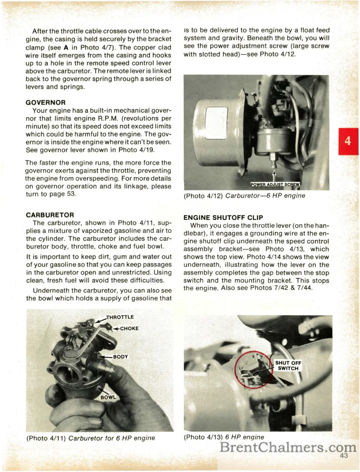
Underneath
the
carburetor,
you
can also see
the bowl
which
holds a
supply
of
gasoline
that
(Photo
4/11)
Carburetor
for
6
HP
engine
is
to
be delivered
to
the engine by a float feed
system and gravity. Beneath
the
bowl, you
will
see
the
power
adjustment
screw (large
screw
with
slotted
head}-see
Photo 4/12.
(Photo 4/12)
Carburetor-6
HP engine
ENGINE SHUTOFF CLIP
When you close the
throttle
lever (on the han-
dlebar),
it
engages a
grounding
wire
at
the
en-
gine
shutoff
clip
underneath the speed
control
assembly
bracket-see
Photo 4/13,
which
shows the
top
view. Photo 4/14 shows
the
view
underneath,
illustrating
how
the
lever
on
the
assembly completes
the
gap between the
stop
switch and
the
mounting
bracket.
This
stops
the engine. Also see Photos 7/42
& 7/44.
(Photo 4/13) 6
HP
engine
43
 Loading...