Fuse Nominal current Description
F50 60A ISOBUS power
F51 25A ISOBUS engine control unit power
F52 125A Cabin main
F53 250A Grid heater
F2.7/E 30A Fuel heater main
F2.7.1/E 5A Fuel heater actuator
F2.7.5/E 15A Fuel heater vehicle fan
Relay Description
K1M Starter relay
K8M
Grid heater relay
1)
K2.5.7/E Fuel heater, HVAC fan
1)
Placed on the left side of the engine.
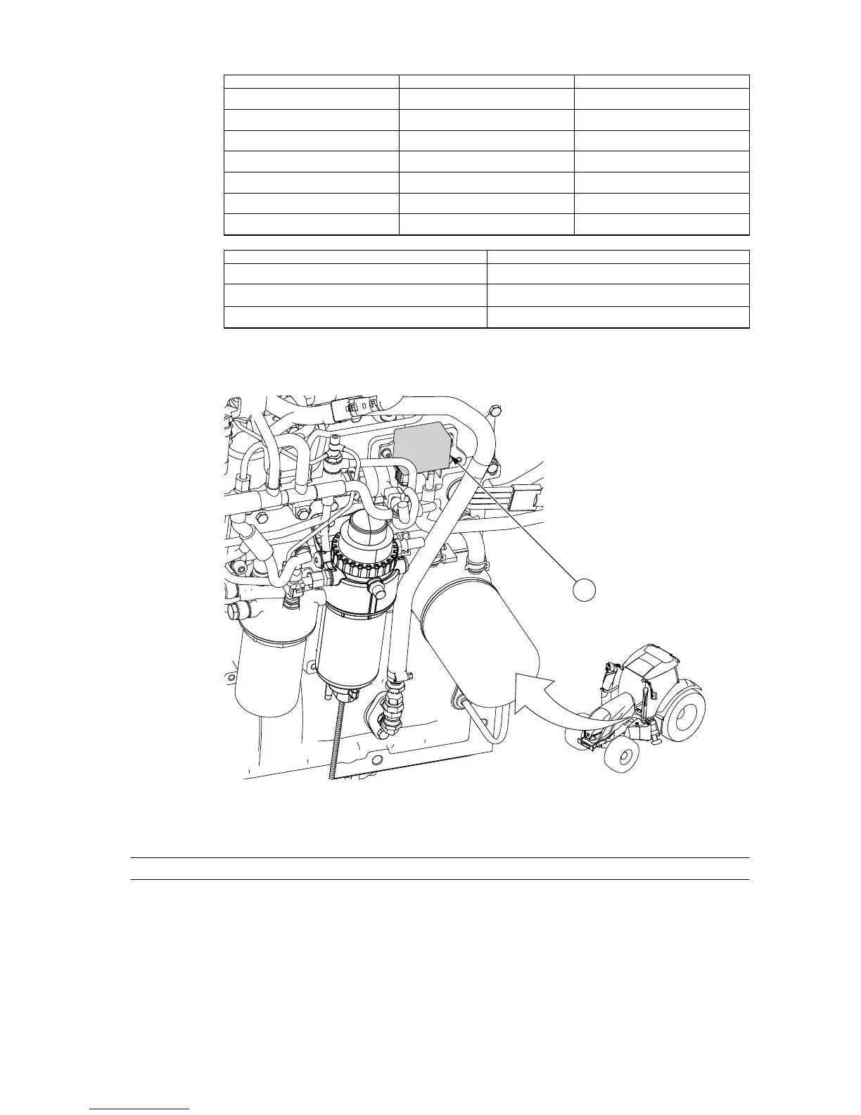
Location of relay K8M
GUID-6134696C-5F40-49EE-839A-D6C406DC48CD
1. Relay K8M
4.8.6.10 Fuses and relays in the engine electric centre
Fuses and relays in the engine electric centre are listed in the following tables.
The fuse diagram is on the reverse side of the electric centre cover. The engine
electric centre contains 10 fuses and 2 empty places for spares. The nominal
current rating of the fuses is 3-25 A.
4. Maintenance
- 355 -
 Loading...