Operating & Mounting instructions – 8 074 143.03/03 – Page 30
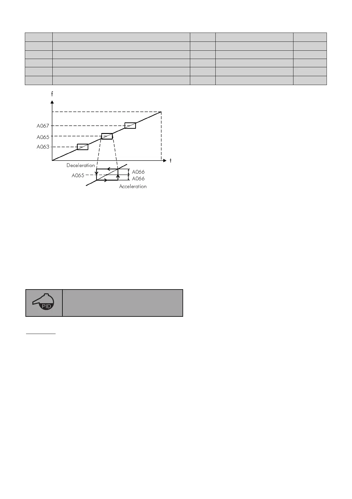
A063
1st Jump frequency VIC 0,00...400,0 Hz 0,00 Hz
A064
1st Jump frequency width VIC 0,00...10,0 Hz 0,50 Hz
A065
2nd Jump frequency VIC 0,00...400,0 Hz 0,00 Hz
A066
2nd Jump frequency width VIC 0,00...10,0 Hz 0,50 Hz
A067
3rd Jump frequency VIC 0,00...400,0 Hz 0,00 Hz
A068
3rd Jump frequency width VIC 0,00...10,0 Hz 0,50 Hz
To avoid possible resonance in the drive system, it is possible to program three jump frequency
ranges using functions A063...A068.
The jump frequency defines the frequency at which the drive should not be operated in steady-state.
The adjustable jump frequency range determines the frequency range faded out and actions
symmetrical to the jump frequency.
General
The PID controller is designed as a process controller with the variable “Frequency [Hz]”, whereby
P (kp), I (T
N) and D (Tv) can be adjusted individually. The reverence and actual value are standardi-
sed in % (range 0...100 %). For better presentation, they can be converted to the individual plant
value using A075 (e.g. flow 0...30 l/h).
The PID controller output is limited with 0 Hz (or A062) at the bottom and with the maximum
frequency A004 (or A061) at the top end. As a result, there is no reversal of the motor in the event
of negative deviation.
In order to optimize the disturbance behaviour of the controller, it is advisable to set the acceleration
and deceleration ramps as small as possible.
PID Configuration
PID
 Loading...