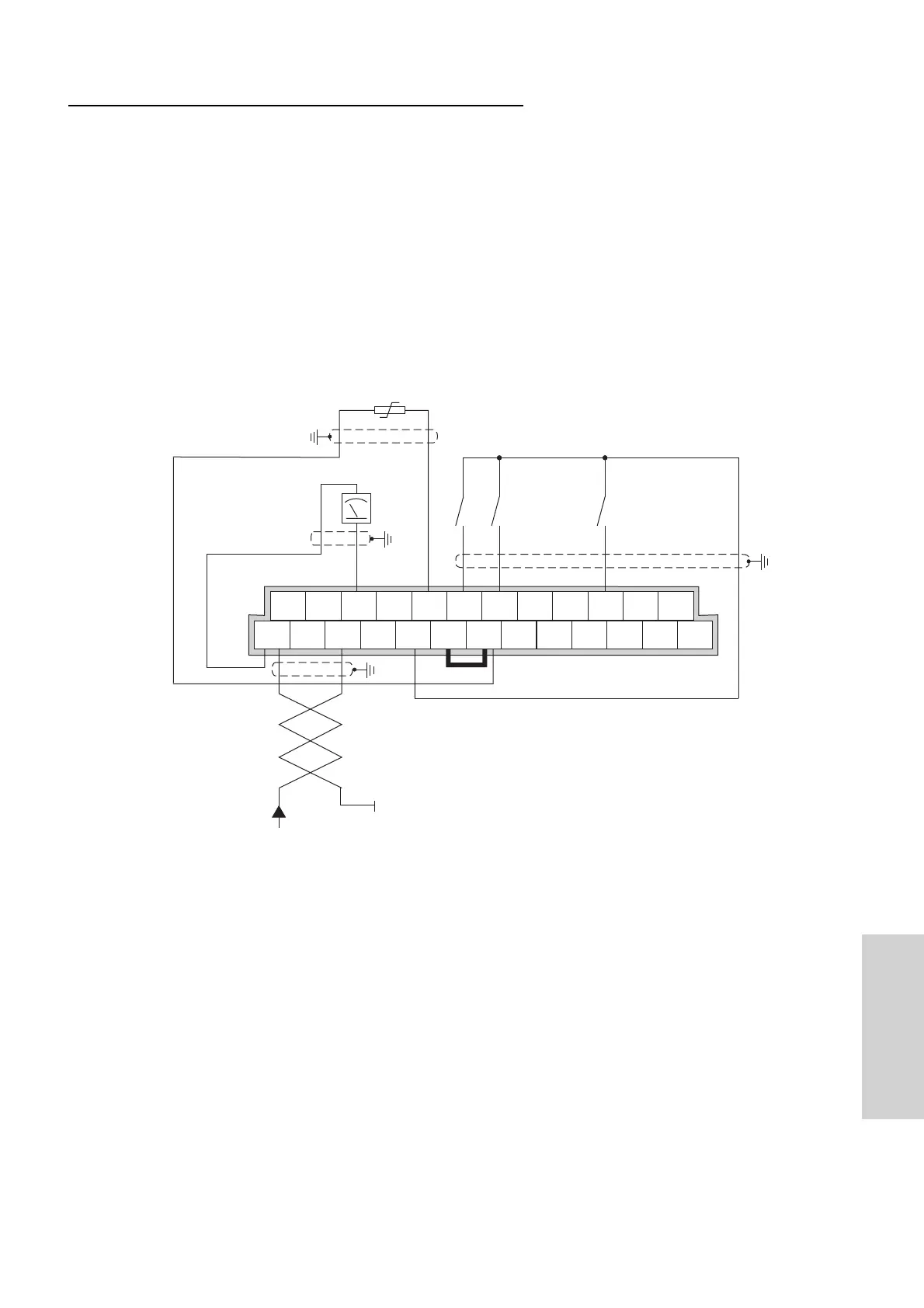
Operation via analog reference value 4...20 mA
Following parameters have to be changed:
A001 = 01 Reference value via control terminals
A002 = 01 Control command via digital input
F002 = 10 s Adjust acceleration time
F003 = 10 s Adjust deceleration time
C002 = 16 AT Switch-over to 4 .. 20 mA reference value with digital input 2
C005 = 01 REV Start reverse on digital input 5
b098 = 01 PTC PTC resistor on thermistor input
b080 = 180 Adjustment of analog display
After setting the parameters, the inverter can be started with clockwise rotation field using terminal
FW or with anti-clockwise rotation field using terminal 5. If both terminals are closed at the same
time, a Stop command is issued to the frequency inverter.
The digital input terminals 2 (parameter setting 16 AT) switches from voltage ref. value to current ref.
value.
*) Instead of fixed or switched wiring to terminal 2, parameter C012 can be set to position 01 (input
for break contact).
The wiring example also includes the integration of a motor PTC protection. Thereby, the use of a
screened control line and separate installation of the motor cable is important!
(Earth the screen on the inverter side only!)
 Loading...