Operating & Mounting instructions – 8 074 143.03/03 – Page 86
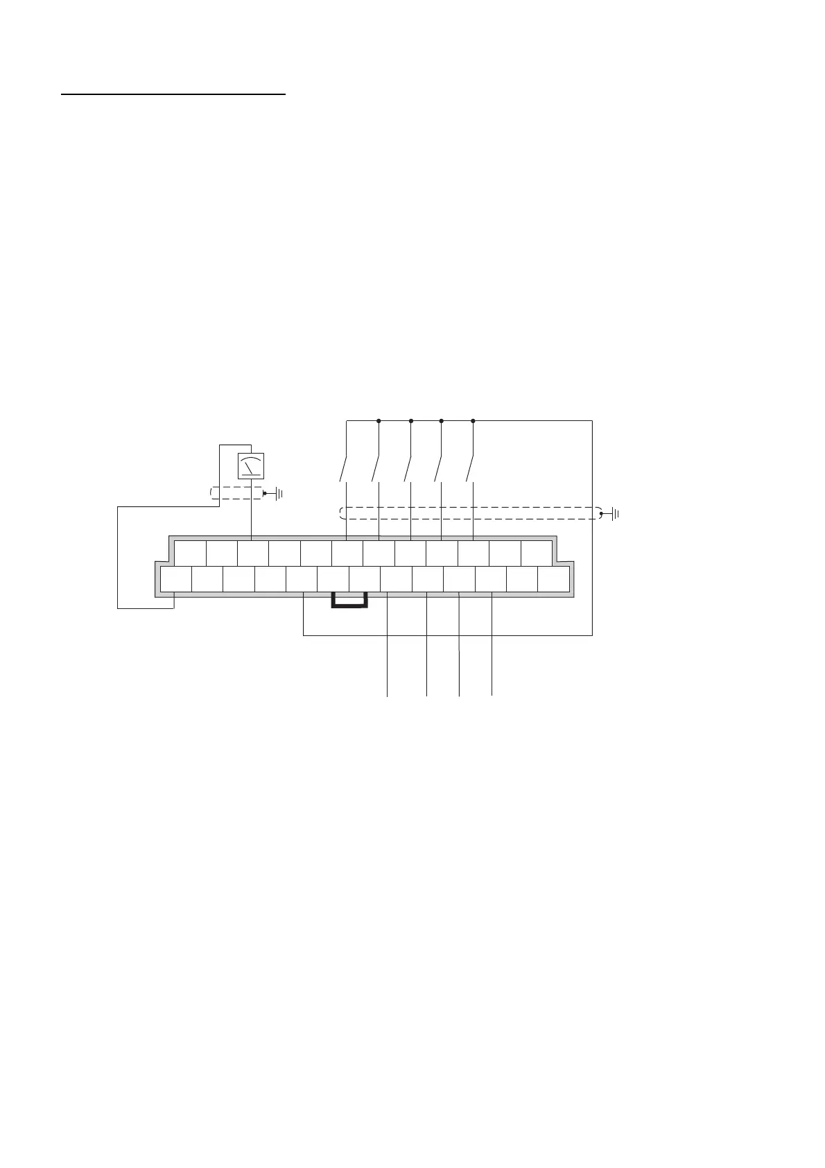
Operation via multispeeds
Following parameters have to be changed:
A001 = 01 Reference value via control terminals
A002 = 01 Control command via digital input
F002 = 10 s Adjust acceleration time
F003 = 10 s Adjust deceleration time
C002 = 16 AT Switch-over to 4 .. 20 mA ref. value with digital input 2
C005 = 01 REV Start reverse on digital input 5
C004 = 02 CF1Multispeed A with digital input 4
C003 = 03 CF2Multispeed B with digital input 3
A021 = Multispeed 1 if Fix A is 1 and Fix B is 0
A022 = Multispeed 2 if Fix A is 0 and Fix B is 1
A023 = Multispeed 3 if Fix A and Fix B are 1
After setting the parameters, the inverter can be started with clockwise rotation field using terminal
FW or with anti-clockwise rotation field using terminal 5. If both terminals are closed at the same
time, a Stop command is issued to the frequency inverter.
If one of the multispeed inputs is activated, the actual ref. value is overruled and the frequency
inverter is accelerated or the motor is slowed down to the new reference setting. If no digital input is
selected, the speed can be defined using the analog inputs.
For the combination of the individual multispeeds, please see the description of parameters F001
and A020 to A035.
The wiring example also includes the parametrization of the relay outputs for terminal 11 and 12 for
external messages.
 Loading...