Operating & Mounting instructions – 8 074 143.03/03 – Page 43
Parameters
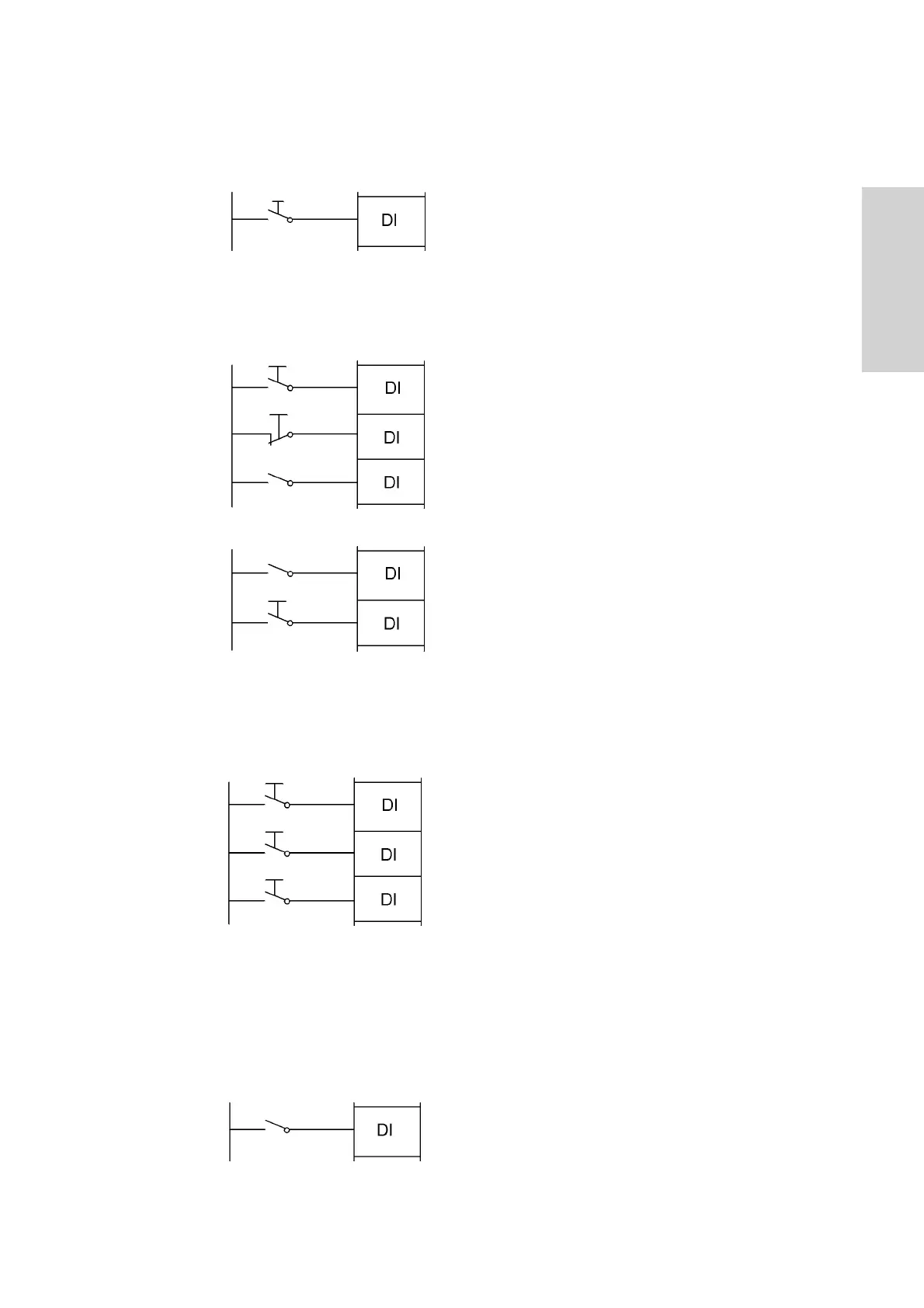
External reset:
Allows you to confirm an error via the terminals.
During operation, an external Reset-command
stops the inverter!! The signal must not be inverted
and must not be issued for more than 4 seconds.
A permanent reset is not possible. If the inverter is
running without problems, it runs to 0 Hz when an
RS signal is issued! In plants, where a common
reset signal is used for all devices, parameter
C102 must be set to position 02 !
Start/Stop via impulses:
An impulse contact (N.O.) leads a Start-command.
An impulse contact (N.C.) leads a Stop-command.
Closing the contact leads to a change of direction.
Contact open = Forward
PID controller:
If the PID controller is activated (A071=1), the
command “PID enable” disables the PID
controller and the PID ref. value acts directly on
the output frequency.
Motorpotentiometer:
Reference values via the motorpotentiometer are
defined via the signals “Motorpot increase” and
“Motorpot decrease”.
Thereby, the reference value is increased and
decreased with the adjusted acceleration/
deceleration time (F002/F003 and F202/F203) as
long as the command is active.
The motorpotentiometer is activated via parameter
A001 = 02.
The command “Motorpot reset” deletes the
reference value, if he is stored with parameter
C101 = 01.
Local control:
By closing this contact, the control via the keypad
is activated. After pressing the RUN key, the
inverter accellerates up to the reference value set
with F001 - independent from A002 “Method of
run command”.
If the contact is closed during operation, the drive
stops first.
18 External reset
20 Start impulse
21 Stop impulse
22 Forward/
reverse
27 Motorpot increase
28 Motorpot decrease
29 Motorpot reset
23 PID enable
24 PID reset
31 Local control
 Loading...