Operating & Mounting instructions – 8 074 143.03/03 – Page 80
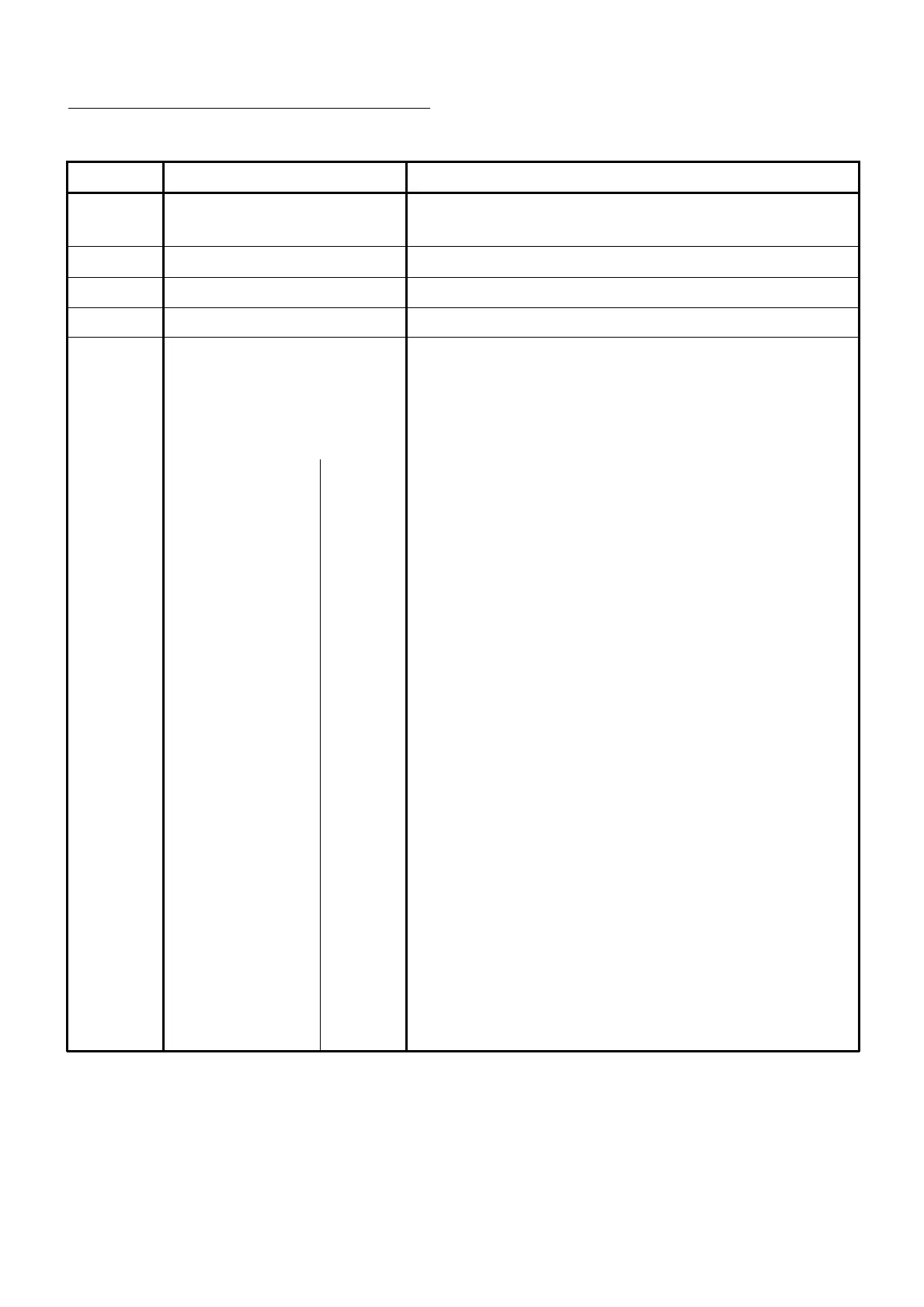
Specification of control terminals
Terminal Function Description
P24 24V 24V potential for digital inputs;
max. load 100 mA
CM1 0V 0V potential for digital inputs
PLC Common Common connection for digital inputs
FW Start RL Starts the inverter in forward direction
1 Programmable approx. 5 mA per input
2 digital inputs The digital inputs 1...5 can be programmed with
3 parameters C001 to C005 as follows
4 (in addition, the inputs can be inverted with parameters
5 C011 to C015):
01 REV
Starts the inverter with anti-clockwise field
02..05 CF1...CF4
Definition of multi-speeds
06 JG
Jog mode
07 DB
DC brake
08 SET
2. parameter set
09 2CH
Activates the 2nd acceleration/decel. time
11 FRS
Impulse lock - idle run
12 EXT
Shut-down due to external fault
13 USP
Prevents restart after undervoltage trip
14 CS
Bypass signal
15 SFT
Prevents the editing of parameters
16 AT
Switch-over to automatic referene value
0...10 V / 4...20 mA
18 RS
External reset
20 STA
Start impulse
21 STP
Stop impulse
22 F/R
Forward/reverse
23 PID
PID enable
24 PIDC
PID reset
27 UP
Motorpot increase
28 DOWN
Motorpot decrease
29 UDC
Motorpot reset
31 OPE
Local control
32...38 SF1...SF7
FIX 1...7
39 OLR
Switch-over of current limitation
NO NO
no use
 Loading...